Finned tube type heat exchanger and manufacturing method thereof

A technology of finned tube type and production method, which is applied in the field of finned tube heat exchanger and its production, and can solve the problems of deformation of heat transfer tube 1 and fin 8, difficulty in penetration of heat transfer tube 1, and strength of expansion rod 11 Insufficient and other problems, to achieve the effect of enhanced pollution resistance and corrosion resistance, simple and reasonable structure, small size

Inactive Publication Date: 2011-05-11
GUANGDONG MIDEA ELECTRIC APPLIANCES CO LTD
View PDF6 Cites 7 Cited by
  • Summary
  • Abstract
  • Description
  • Claims
  • Application Information

AI Technical Summary

Problems solved by technology

In the actual production process, it will become quite difficult for the heat transfer tube 1 to penetrate multiple fins 8, and it will easily lead to deformation of the heat transfer tube 1 and the fins 8
In addition, when the diameter of the heat transfer tube 1 becomes smaller, the expansion of the heat transfer tube 1 needs to overcome greater resistance, and the expansion rod 10 connected to the expansion head 11 must be correspondingly thinner, which will cause the expansion rod 11 to Insufficient strength and deformation

Method used


Image

  • Finned tube type heat exchanger and manufacturing method thereof
  • Finned tube type heat exchanger and manufacturing method thereof
  • Finned tube type heat exchanger and manufacturing method thereof

Examples


no. 1 example

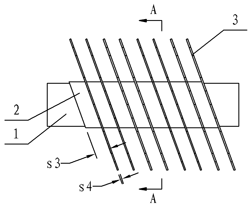
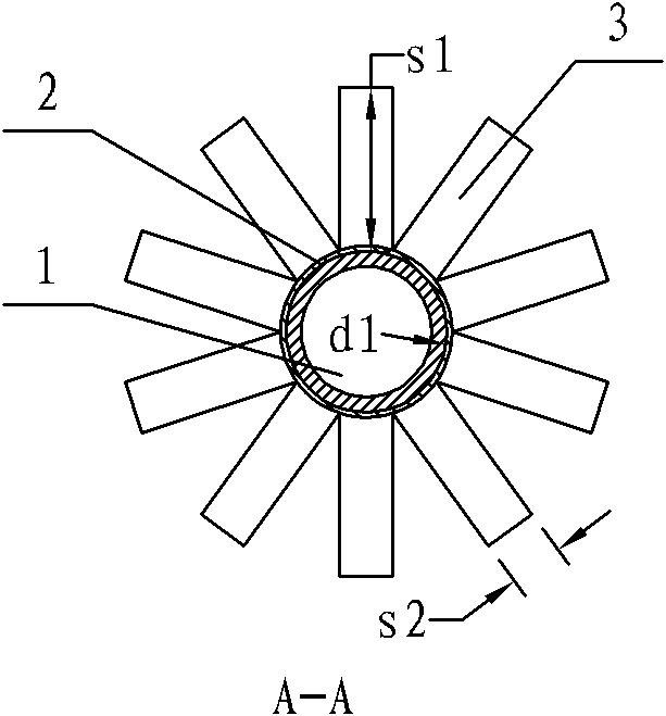
[0035] see Figure 1-Figure 2 In this finned tube heat exchanger, fins are continuously and tightly wound in a spiral shape on the outside of the heat transfer tube 1 whose outer diameter d1 is less than or equal to 5 mm.

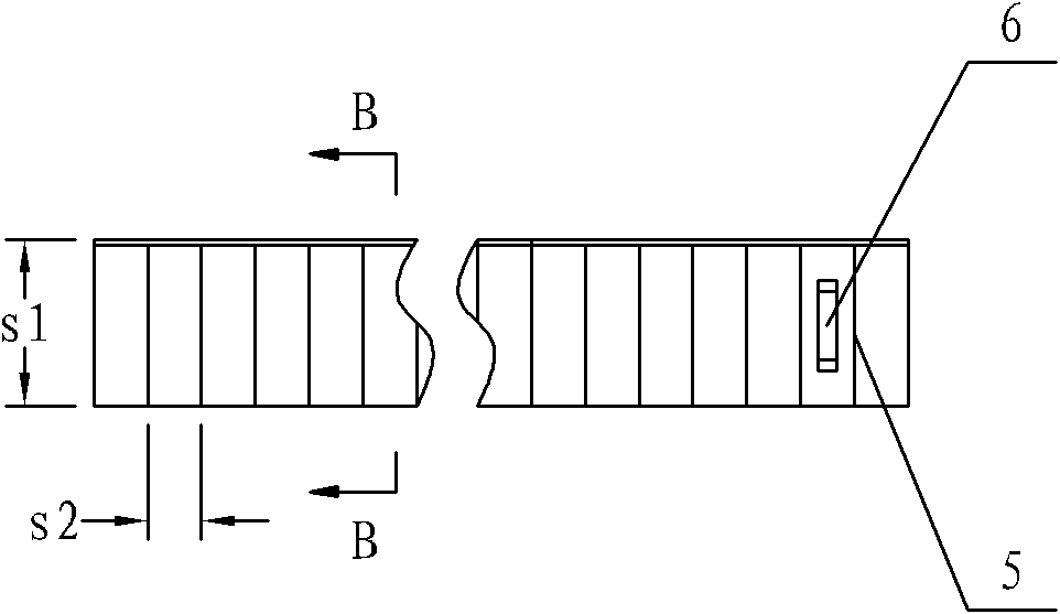
[0036] The fins include more than two fin bodies 3 arranged on the fin base 2, two adjacent fin bodies 3 are separated from each other, and a knuckle α is provided between the fin base 2 and the fin body 3, The knuckle angle α is generally 90 degrees. The fin base strip 2 is closely attached to and wound on the surface of the heat transfer tube 1 in a spiral shape. The fin body 3 is connected with the fin base 2 and is approximately at right angles to the wall surface of the heat transfer tube 1 . Generally, the included angle between the fin body 3 and the axial direction of the heat transfer tube 1 is ≤90°.

[0037] The finned base belt 2 is closely attached to the heat transfer tube 1, and the step size of each round of the finned base belt 2 winding ...

no. 2 example

[0054] see Figure 10 , to illustrate the second embodiment of the present invention. For the finned tube heat exchanger using flat tubes 12, it is also difficult to expand the tubes. However, the tube expansion problem can be well solved by adopting the method of wrapping the fins of the present invention. Similar to the first embodiment, the fin with the fin base strip 2 and the fin body 3 is tightly wound on the surface of the flat tube 12 in a spiral manner from the fin winding starting point 13, and finally the The other end of the fin base strip 2 is welded on the surface of the flat tube 12 . In order to prevent the fins from being broken due to the relatively large angle change at the corners when winding the fins at the four corners of the flat tube 12, it should be used such as Figure 10 Shown is a flat tube with rounded corners. The size of the radius R of the fillet ≥ the width s2 of the fin body.


PUM

PropertyMeasurementUnit
widthaaaaaaaaaa
thicknessaaaaaaaaaa

Abstract

The invention relates to a finned tube type heat exchanger and a manufacturing method thereof. The finned tube type heat exchanger provided by the invention comprises fins and a heat transfer tube, wherein the fins comprise more than two fin bodies arranged on a fin base band; the two adjacent fin bodies are mutually separated; folding angles are formed between the fin base band and the fin bodies; the fin base band is tightly attached on and wound on the surface of the heat transfer tube in a spiral shape; the step length of each circle of the fin base band wound on the heat transfer tube is larger than or equal to the width of the fin base band, and the width is between 0.5mm and 3mm; the ratio of the height of the fin bodies to the outer diameter of the heat transfer tube is between 0.5 and 2; the number of the fin bodies is larger than or equal to 10 when per circle of the fin base band is wound on the heat transfer tube; the included angle between the fin bodies and the axis direction of the heat transfer tube is less than or equal to 90 degrees; and a hydrophilic coating is painted on the surfaces of the fins. The invention has the characteristics of simple and reasonable structure, no need of tube expansion, strong heat exchange capability, simple processing process, and small volume of the heat exchanger provide by the invention, and is flexible in operation.

Description

technical field [0001] The invention relates to a finned tube heat exchanger and a manufacturing method thereof. Background technique [0002] In order to improve the performance of the heat exchanger, reduce the production cost of the heat exchanger, reduce the volume of the heat exchanger, and adopt a heat transfer tube with a smaller diameter are the current research focus of the heat exchanger. In addition, the small-diameter heat transfer tube has better pressure resistance, which can further reduce the wall thickness of the tube and reduce the cost of materials. [0003] See attached Figure 7 - attached Figure 9 , The traditional finned tube heat exchanger for air conditioners includes a plurality of fins 8 arranged in parallel, and the fins 8 are provided with insertion holes 9 for the heat transfer tubes 1 to pass through vertically. There is a gap s8 between the outer diameter d1 of the heat transfer tube 1 and the inner diameter d2 of the insertion hole 9 . Af...

Claims


Application Information

Patent Timeline
Patent Type & Authority Applications(China)
IPC IPC(8): F28F1/36F28F19/02B23P15/26
Inventor 岳宝张智贾庆贤曾昭顺赵夫峰伍光辉
Owner GUANGDONG MIDEA ELECTRIC APPLIANCES CO LTD
Why Eureka
Try Eureka