High-precision wide-range low-coherent interference shift demodulation device and demodulation method thereof

A low-coherence interference, large-range technology, applied in the field of displacement information demodulation, can solve the problems of limited pixels of linear array CCD, small measurement range, poor long-term reliability and stability, etc., to achieve high reliability and wide application range. Effect

Inactive Publication Date: 2011-05-11
TIANJIN UNIV
View PDF4 Cites 35 Cited by
  • Summary
  • Abstract
  • Description
  • Claims
  • Application Information

AI Technical Summary

Problems solved by technology

[0003] The time scanning method can measure a large range, but due to the need to mechanically scan one of the mirrors, its long-term reliability and stability are poor, and the measurement accuracy is only on the order of mi

Method used


Image

  • High-precision wide-range low-coherent interference shift demodulation device and demodulation method thereof
  • High-precision wide-range low-coherent interference shift demodulation device and demodulation method thereof
  • High-precision wide-range low-coherent interference shift demodulation device and demodulation method thereof

Examples


Embodiment 1

[0039] Embodiment 1: A high-precision, large-range and low-coherence interference displacement demodulation device

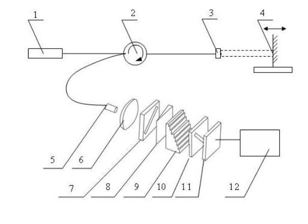
[0040] Such as figure 1 As shown, the light emitted by the broadband light source 1 passes through the optical circulator 2 and reaches the self-focusing collimating lens 3 on the sensor side, part of the light is reflected by the end reflective surface of the self-focusing collimating lens 3, and the other part of the light is self-focusing and collimating The lens 3 is collimated and emitted to the fixed mirror 4 fixed on the object to be detected, and after being reflected, this part of the light is coupled into the optical fiber again. The reflected two beams of light are transmitted to the beam expander lens 6 through the optical circulator 2 and the optical fiber connector 5 , and the optical fiber connector 5 is located on the focal length of the beam expander lens 6 to realize beam expansion and penetrate the effective photosensitive area of ​​the area ...

Embodiment 2

[0042] Embodiment 2: A high-precision, large-range and low-coherence interference displacement demodulation method

[0043] The demodulation process of the above-mentioned low-coherence interference displacement demodulation device is as follows:

[0044] figure 1 The light from the broadband light source 1 in the sensor passes through the optical circulator 2 and reaches the self-focusing collimating lens 3 on the sensing side, part of the light is reflected by the end face reflection surface of the self-focusing collimating lens 3, and the other part of the light is reflected by the self-focusing collimating lens 3 The collimated light is emitted to the fixed mirror 4 of the object to be detected, and after being reflected, this part of the light is coupled into the optical fiber again, and the two parts of the light have an optical path difference related to the displacement of the object to be detected , It is twice the distance between the self-focusing collimating...

Embodiment 3

[0055] Embodiment 3: application example

[0056] If the self-focusing collimating lens 3 and the fixed mirror 4 are used as the two reflection surfaces of the fiber optic Fab, the demodulation device and demodulation method can be used for the absolute cavity length demodulation of the fiber Fab. Taking the fiber-optic F-Per pressure sensor as an example, the fixed reflector 4 is fixed on the pressure diaphragm. When the F-P cavity length is small enough, the self-focusing collimating lens 3 can be omitted, and the optical fiber can be directly used instead, that is, the fixed reflector The mirror 4 and the end face of the fiber form a Fab cavity. When the external pressure acts on the diaphragm, the diaphragm deforms, driving the mirror 4 to move axially, and the demodulation device can match the current F-P cavity length through optical path difference scanning, thereby sensing the deformation of the diaphragm, and then according to The formula or calibration factor calc...


PUM


Abstract

The invention relates to a high-precision wide-range low-coherent interference shift demodulation device, which comprises a light source, an optical circulator, a self-focusing collimation lens, a fixed reflecting mirror, an optical fiber splicer, a beam extender lens, a polarizer, a birefringent optical wedge, a stair-shaped birefringent phase shifter, an analyzer, a planar array camera and a processing unit. A demodulation method comprises the following steps: dividing the light emitted from the light source into two parts after the light passes through the optical circulator and reaches the self-focusing collimation lens at the sensing side, wherein one part is directly reflected and the other part is reflected after entering the reflecting mirror fixed on an object to be detected, and the two parts of reflection light have an optical path difference (OPD); guiding the two parts of reflection light to pass through the optical circulator again so as to reach the optical fiber splicer and then reach the birefringent optical wedge and the stair-shaped birefringent phase shifter through the beam extender lens and polarizer; realizing the wide-range optical path difference (OPD) scanning under the combined action of the birefringent optical wedge and the stair-shaped birefringent phase shifter; generating an interference fringe behind the analyzer; receiving the interference fringe by using the planar array camera; and detecting the shift information through digital processing by a computer or an embedded system.

Description

technical field [0001] The invention relates to the field of displacement information demodulation. The displacement sensing demodulation method can be used for high-precision detection of displacement, or demodulation of other sensors such as strain, temperature, thickness, group refractive index and pressure that can be converted into displacement. Background technique [0002] The low-coherence interferometry technology used for displacement demodulation mainly includes time-scanning and space-scanning. The time-scanning method such as Miho Song et al. (Minho Song, Byoungho Lee, An effective optical evaluation technique using visible low-coherence interferometry, Optics and Lasers in Engineering, 1997, 27:441-449) conducts the The optical path difference is scanned to match the displacement to be measured. The space scanning type is to make a linear distribution of the optical path difference in space, so that the space scanning of the optical path difference can be real...

Claims


Application Information

Patent Timeline
IPC IPC(8): G01B11/02G01B9/00G02F2/00G02B5/30
Inventor 江俊峰刘铁根刘琨尹金德
Owner TIANJIN UNIV
Why Eureka
Try Eureka