Tester for thrust bearing

A test device and thrust bearing technology, which is applied in the direction of mechanical bearing testing, etc., can solve the problems of high installation accuracy, difficult processing of test pieces, and low degree of automation, so as to achieve easy maintenance and adjustment without gaps, and a high degree of automation Effect

Active Publication Date: 2011-05-11
CHINA PETROLEUM & CHEM CORP +1
View PDF5 Cites 59 Cited by
  • Summary
  • Abstract
  • Description
  • Claims
  • Application Information

AI Technical Summary

Problems solved by technology

In addition, downhole drilling and production tools have a wide variety of specifications and various size series, resulting in an increase in the specification range required for thrust bearings
These factors have made the measurement of this type of thrust bearing difficult and the measurement data is inaccurate
[0004] In the current prior art, the patent No. ZL95208823.1 discloses a sliding thrust bearing online instantaneous wear measurement testing machine for sliding thrust bearings. Its working principle is through the principle of lever loading and lever The online wear measurement of the sliding thrust bearing is realized by the displacement change, but it has the following disadvantages: (1) The load range of the thrust bearing is small, the load change adjustment is inconvenient, and the heavy-duty thrust bearing test is not easy to realize; (2) The motor rotates directly, It is inconvenient to adjust the rotation speed and driving torque; (3) The leverage principle is used to load and measure, and the accuracy is not easy to guarantee; (4) The measurement data is read manually, and the degree of automation is low
[0005] The patent No. US6199425B1 discloses a testing machine for the rotation test of thrust bearings. Its working principle is to use the magnetic force or air-fluid loading principle and the motor-driven testing device installed in rows to rotate, but it has the following disadvantages: ( 1) It is suitable for low-load, high-speed bearing tests, and cannot test heavy-duty bearings; (2) The specifications and sizes of the tested bearings are relatively small; (3) The installation of the test bearings is inconvenient and requires high installation accuracy
[0006] The application with the publication number CN1828264A discloses an online measurement and testing machine for friction and wear of radial sliding bearings, including several parts such as drive, loading, test device and signal acquisition. The motor drives the test piece to rotate, and the sensor is used to collect the test data, but it has the following disadvantages: (1) The test sample must be processed into a specified size, which limits the application range of the testing machine; (2) The leverage principle is used to load and measure , the accuracy is not easy to guarantee; (3) The disassembly and assembly of the test piece is inconvenient, and the processing of the test piece is difficult
[0007] The prior art literature ("Large Radial and Thrust Sliding Bearing Test Bench Structure Design and Application", Hu Chaoyang et al., Qiqihar University Journal, 2005.6, Volume 21, No. 2, P80-82) discloses a radial bearing Composite test bench for thrust bearing test, including drag mechanism, body, loading mechanism, lubricating oil system and measurement system, etc., its working principle is to load the test piece through the hydraulic cylinder, and drive the test piece to rotate by the frequency conversion motor. And adopt the sensor to collect test data, but it has the following deficiencies: (1) the test main shaft of this test device is horizontal, when carrying out the radial test bearing test, it is easy to cause the instability of the main shaft; (2) the test device When the test spindle is used for the thrust test bearing test, the installation of the test bearing is inconvenient
[0008] Due to the above deficiencies in the prior art, there is currently no special test equipment for thrust bearings used in downhole drilling tools

Method used


Image

  • Tester for thrust bearing
  • Tester for thrust bearing
  • Tester for thrust bearing

Examples


Embodiment Construction

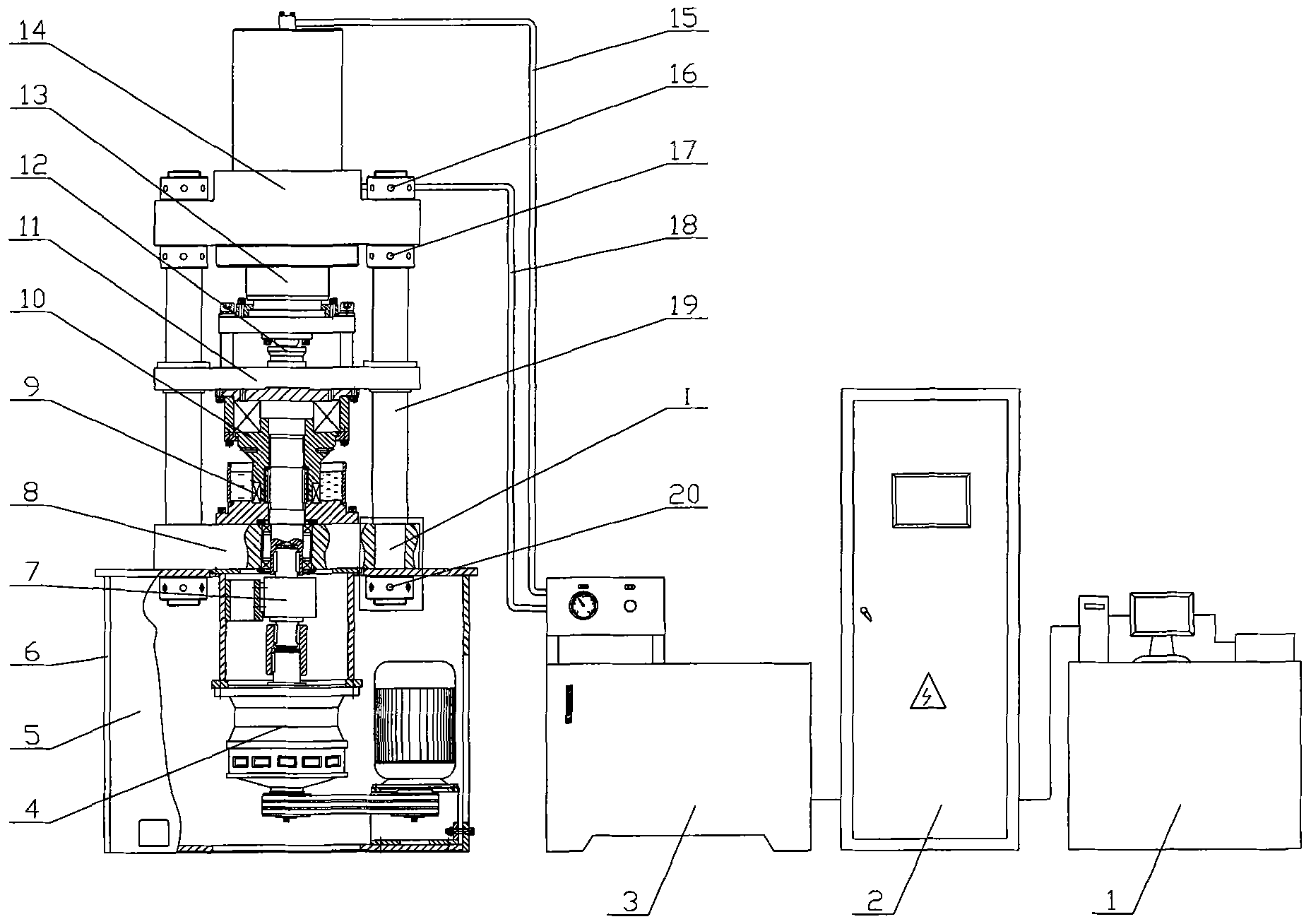
[0040] like figure 1 As shown, a thrust bearing test device includes a loading system 13 , a test bench component 10 , a rotary transmission system 4 and a frame component 5 .

[0041] The loading system 13, the test bench part 10 and the rotary transmission system 4 are based on the frame part 5, and are installed on it in a vertical order: the loading system 13 is installed above the test bench part 10, rotates The transmission part 4 is installed under the test bench part 10 . The loading system 13 , the test bench part 10 and the rotation transmission part 4 are installed on the frame part 5 . The loading system 13 is connected to the test bench part 10 which is connected to the rotary transmission part 4 . The loading system 13 provides the load required for the test, and the rotating transmission part 4 provides the power and speed of the test.

[0042] The frame component 5 includes a frame platform 6 , a frame bottom plate 8 , a frame drag plate 11 , a frame top pla...


PUM


Abstract

The invention provides a tester for a thrust bearing, comprising a loading system (13), a test bed component (10), a rotary transmission system (4), an electric system and a control system, wherein the loading system (13), the test bed component (10) and the rotary transmission system (4) are arranged on a stand component (5). The stand component (5) is taken as a basic frame, and the loading system (13) is vertically installed above the test bed component (10). A test press head (40) at the lower section of the test bed component (10) is pressured by a piston of a hydraulic cylinder (25), wherein a test bearing (9) is positioned on the test press head (40). The rotary transmission component (4) is arranged below the test bed component (10) to drive the test press head (40) to rotate by a transmission main shaft (39); and the running situations of the test bearing (9) are tested under the condition of setting parameter sum by utilizing a pressure sensor (12) and a torsion sensor (7). The tester is applied to testing a heavy-load thrust bearing with irregular size, has high degree of automation, and can properly control the feedback by a computer.

Description

technical field [0001] The invention belongs to the field of test devices for testing bearing performance, and in particular relates to a thrust bearing test device. Background technique [0002] Bearings are the basic and key components widely used in mechanical products, and their performance plays a vital role in product quality. Especially for downhole tools used in oil drilling, the reliability of their bearings plays a key role in the smooth implementation of drilling operations. Therefore, more and more attention is paid to the quality and reliability of bearings, and the life test and performance evaluation of bearings are regarded as the top priority, especially for bearings under special working conditions, the performance test has become the key to the quality control of the whole set of tools link. [0003] With the rapid development of the world's petroleum industry, drilling and production operations are increasing, and the reliability requirements for downho...

Claims


Application Information

Patent Timeline
Patent Type & Authority Applications(China)
IPC IPC(8): G01M13/04
Inventor 郭朝辉马兰荣马开华郑晓志阮臣良
Owner CHINA PETROLEUM & CHEM CORP
Why Eureka
Try Eureka