Spare power automatic switching method for 220kV side circuit and bus of 220kV transformer station

A 220kv, bus-connection standby automatic switching technology, applied in the direction of circuit devices, electrical components, emergency power supply arrangements, etc., can solve difficult promotion, limited adaptability of system operation mode, difficulty in acceptance of standby automatic switching devices and operation management workload and other issues to achieve the effect of improving reliability and adaptability

Active Publication Date: 2011-05-11
GUANGDONG POWER GRID POWER DISPATCHING CONTROL CENT
View PDF4 Cites 40 Cited by
  • Summary
  • Abstract
  • Description
  • Claims
  • Application Information

AI Technical Summary

Problems solved by technology

[0003] However, due to different construction periods, different manufacturers' programming tools, and different logical functions required by the site, etc., the design of the standby automatic switching device is quite different, and they are all aimed at specific substation construction. The adaptability is also very limited. For different operation modes, it is necessary to design different corresponding standby automatic switching devices, which brings great difficulty and workload to the acceptance and operation management of the standby automatic switching devices. It is urgent to strengthen and improve its design standards

Method used


Image

  • Spare power automatic switching method for 220kV side circuit and bus of 220kV transformer station
  • Spare power automatic switching method for 220kV side circuit and bus of 220kV transformer station
  • Spare power automatic switching method for 220kV side circuit and bus of 220kV transformer station

Examples


Embodiment Construction

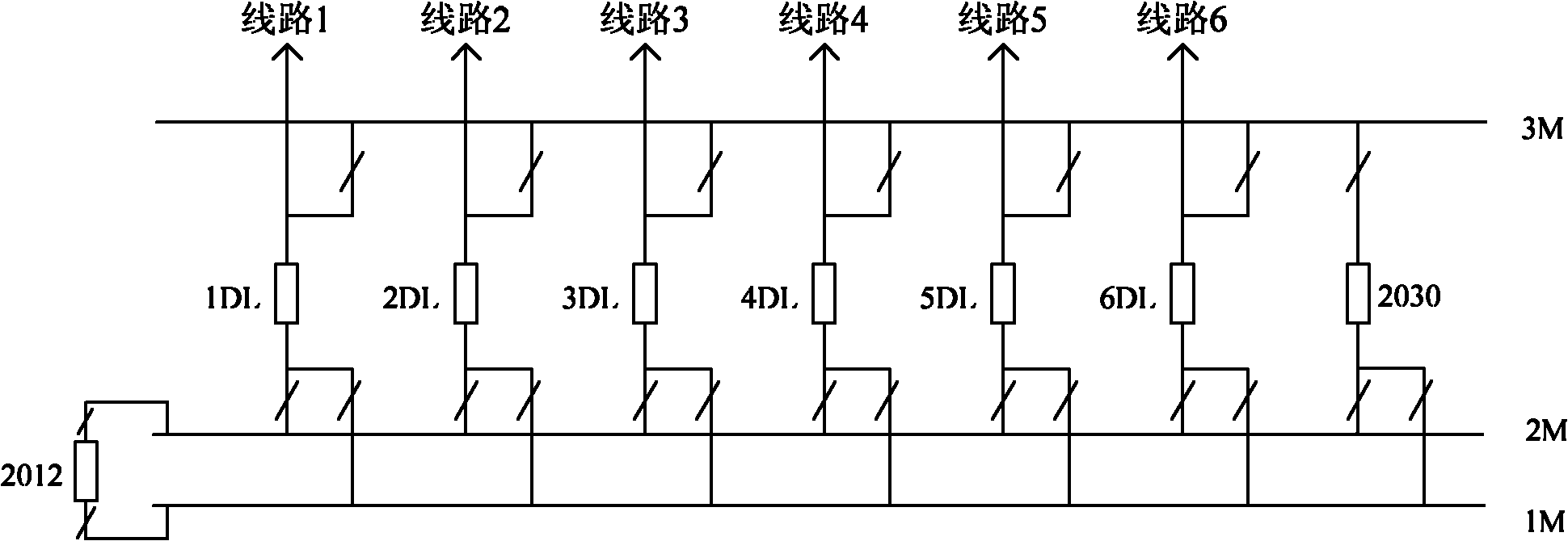
[0016] For the 220kV substation with partition measures, the main wiring forms on the 220kV side are different, and the conventional ones have double busbars with bypass (the simplified wiring diagram is as follows figure 1 As shown), double busbars and single section of double busbars, etc., under various main wiring forms, the main power supply of the 220kV busbars is generally the 220kV line of the station.

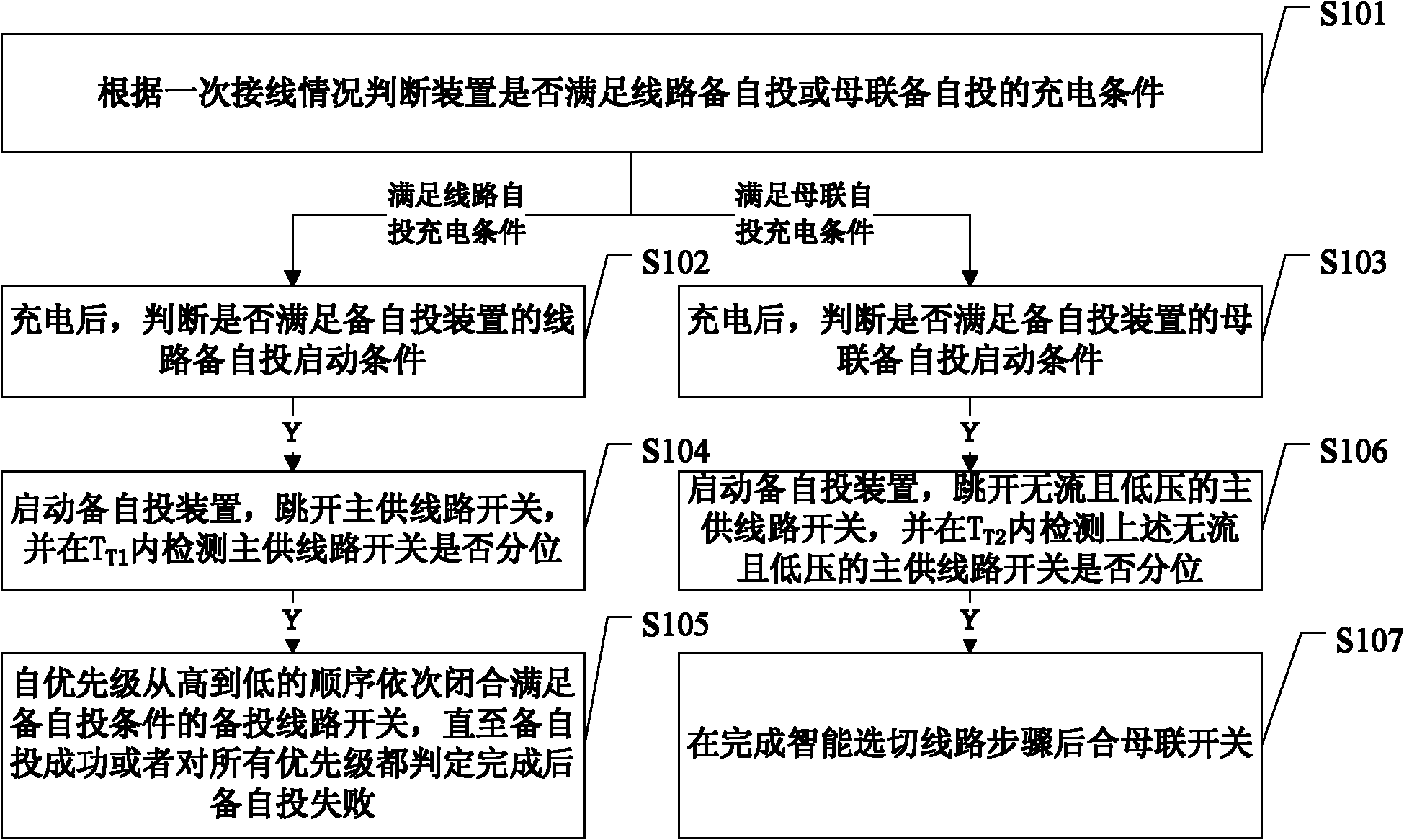
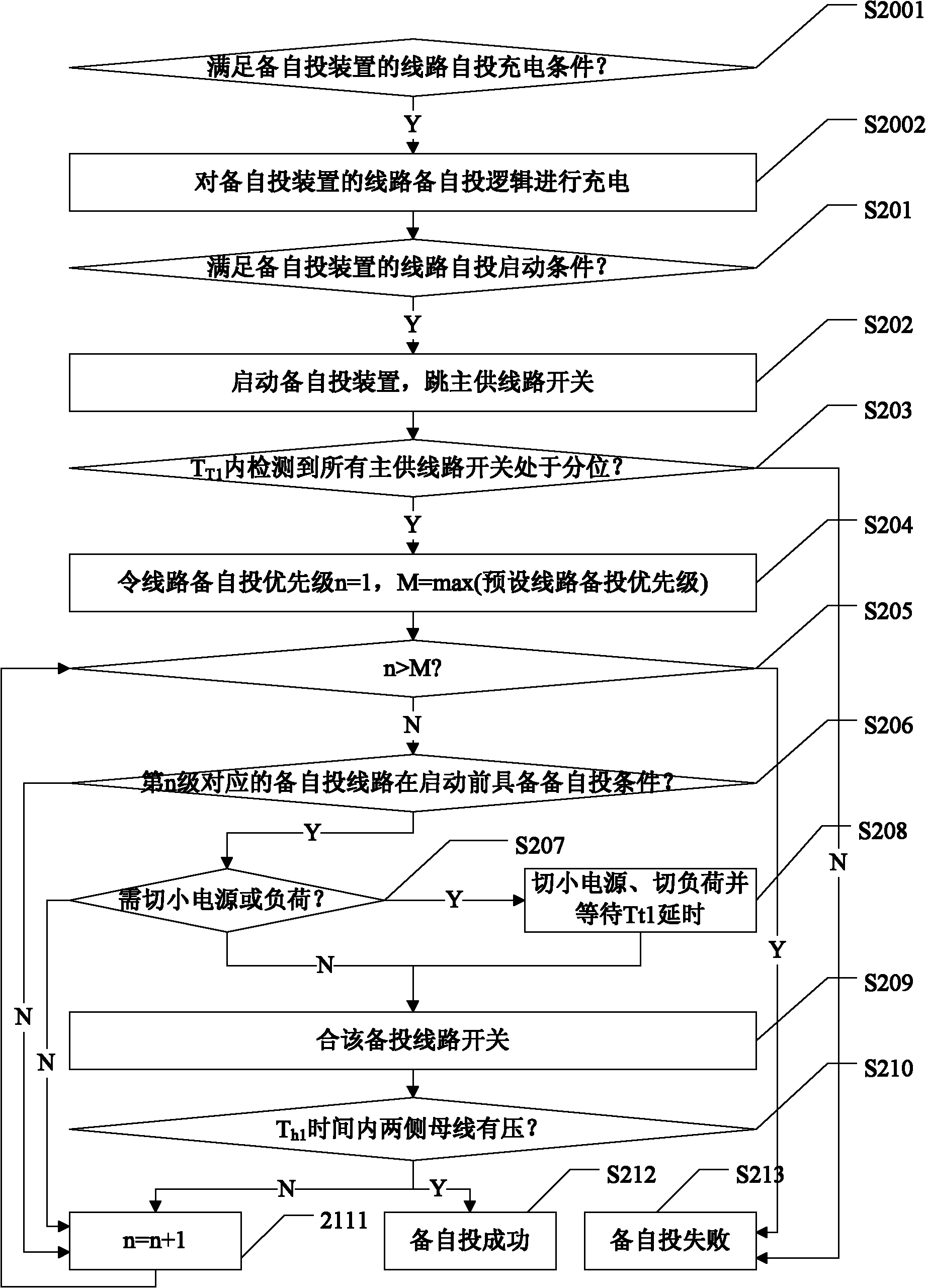
[0017] Accordingly, the present invention aims to design and provide a 220kV side line and busbar backup self-switching method of a 220kV substation, which can be applied to the conventional main wiring form of the 220kV side of a 220kV substation, and can be used as a standardized backup self-switching method , can play a role in various possible operation modes in actual operation, that is, for a site where 220kV busbars operate separately or take 220kV line hot standby to realize zoning measures, when all working power sources in a certain mode trip, according to the...


PUM


Abstract

The invention provides a spare power automatic switching method for a 220kV side circuit and a bus of a 220kV transformer station, comprising the following steps: judging whether a device satisfies the circuit or bus coupler automatic switching charging conditions or not according to the primary wiring conditions and a device setting valve; if the device satisfies the circuit automatic switching charging conditions, judging whether the device satisfies the circuit automatic switching starting conditions or not after charging; if so, starting a spare power automatic switching device, tripping a main supply circuit switch, detecting whether the main supply circuit switch is in the sub-position or not in TT1 (transit time 1), if so, orderly closing a spared switching circuit switch which satisfies the spare power automatic switching conditions under condition of intelligently selecting the circuit in a order of from high to low of the spare power automatic switching priority until the spare power automatic switching is successful or the spare power automatic switching is failed after the judgment on the spare automatic switching priority is finished; and if the device satisfies the bus coupler automatic switching charging conditions, judging whether the device satisfies the bus coupler automatic switching starting conditions or not after charging, if so, starting the spare power automatic switching device, tripping the main supply circuit switch which is free of current and low in voltages, and detecting whether the main supply circuit switch which is free of current and low in voltages is in the sub-position or not in TT2 (transit time 2), if so, combining bus coupler switches after intelligently switching the circuit.

Description

technical field [0001] The invention relates to the technical field of electric power system and automation thereof, in particular to a 220kV side line and busbar backup self-injection method of a 220kV substation. Background technique [0002] With the continuous improvement of the west-to-east power transmission capacity of China Southern Power Grid, the rapid development of power supply and grid construction in the grid, the problem of short-circuit current in the grid is becoming more and more serious. Structural curtailment of power grids. In order to effectively reduce the short-circuit current and optimize the power flow distribution, more and more areas have to adopt the power supply method of de-looping and partitioning. Although the partitioned power supply through substation busbar operation and tie-line hot standby can effectively reduce the power consumption of related sites. The problem of short-circuit current reduces the power supply reliability of the site ...

Claims


Application Information

Patent Timeline
Patent Type & Authority Applications(China)
IPC IPC(8): H02J9/06
Inventor 杨文佳陈兴华李剑辉吴国炳李力陈锦昌杨银国李新超钱峰
Owner GUANGDONG POWER GRID POWER DISPATCHING CONTROL CENT
Why Eureka
Try Eureka