
Power supply device for driving electric motor

A power supply device and motor technology, which is applied to output power conversion devices, electrical components, and AC power input is converted into DC power output, etc., which can solve the problems of instantaneous regenerative power increasing, capacity decreasing, and inability to fully regenerate, etc. The effect of suppressing current distortion

Active Publication Date: 2014-11-26
SANYO DENKI CO LTD
View PDF6 Cites 0 Cited by
  • Summary
  • Abstract
  • Description
  • Claims
  • Application Information

AI Technical Summary

Problems solved by technology

In this conventional power supply device, when the instantaneous regenerative power from the motor M becomes large and the capacity of the drive power supply device becomes small, sufficient regeneration cannot be performed.

Method used


Image

  • Power supply device for driving electric motor
  • Power supply device for driving electric motor
  • Power supply device for driving electric motor

Examples


Embodiment Construction

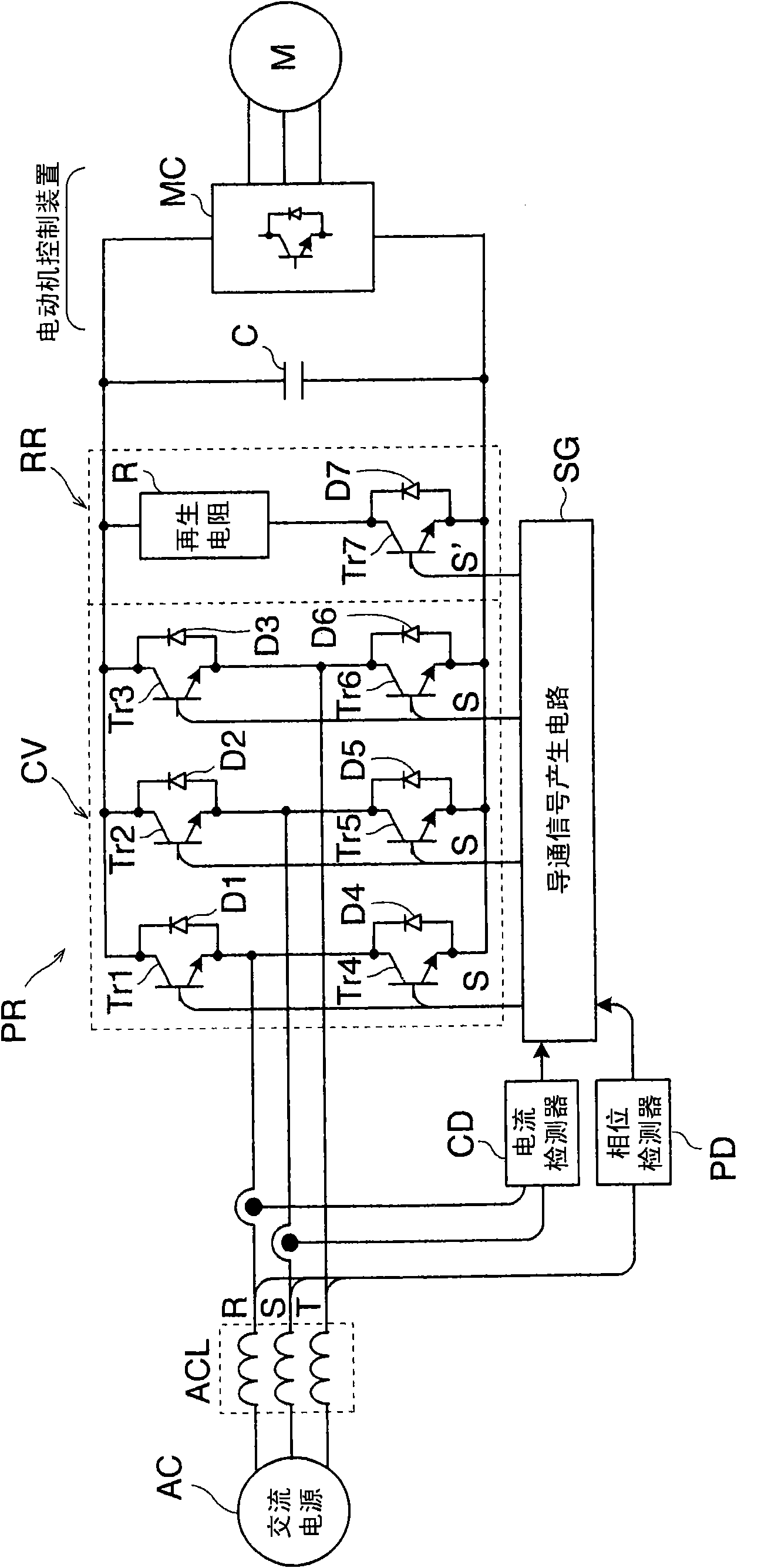
[0034] An example of an embodiment of the present invention will be described in detail below with reference to the drawings. figure 1 It is a figure which shows the outline structure of an example of embodiment of the power supply apparatus for driving the motor of this invention. An AC choke coil ACL is connected to a three-phase AC power supply AC, and transistors Tr1 to Tr6 as six semiconductor switching elements are bridge-connected to the output side thereof to form a converter circuit CV. Furthermore, six diodes D1 to D6 are connected in parallel to the six transistors Tr1 to Tr6 respectively. The six diodes D1 to D6 constitute a bridge-connected three-phase rectifier circuit. The power regeneration circuit PR is constituted by bridge-connected transistors Tr1 to Tr6 and diodes D1 to D6.

[0035] A series circuit of a regenerative resistor R and a parallel circuit of a transistor Tr7 and a diode D7 constituting a switching circuit is connected in parallel between the ...


PUM


Abstract

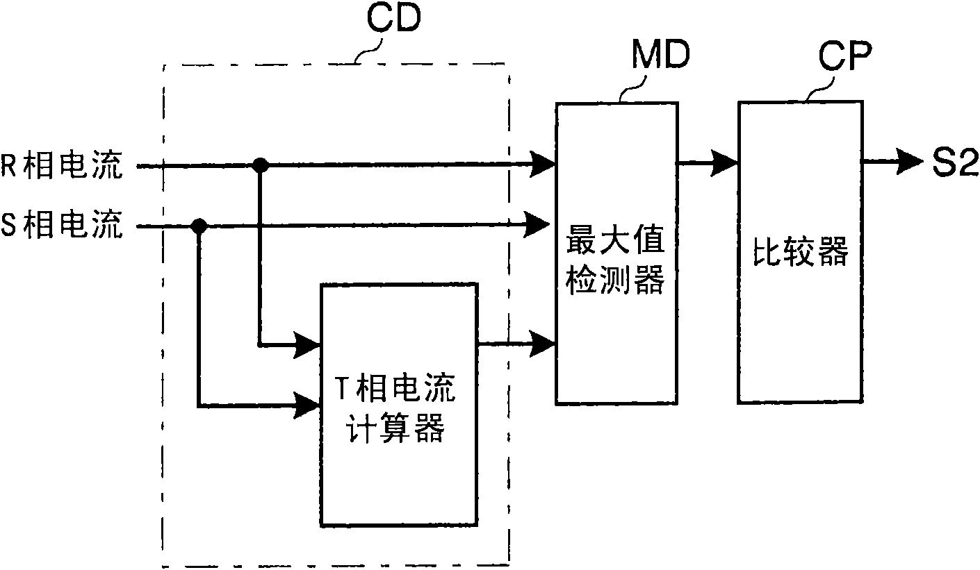
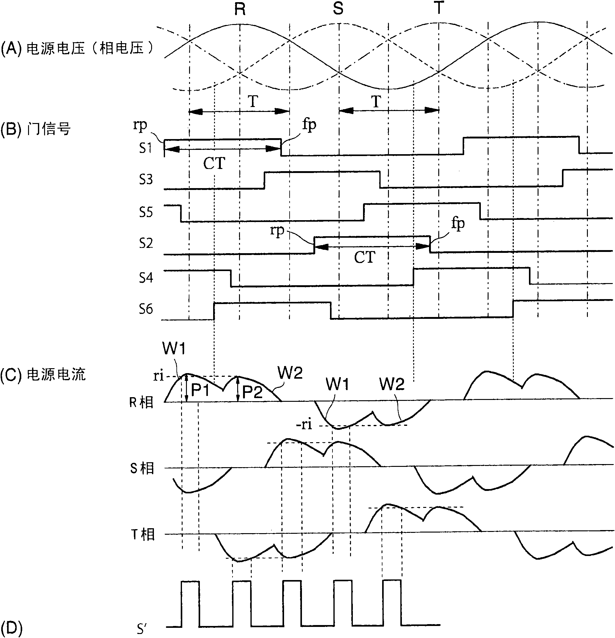
The invention provides a power supply device for driving an electric motor, wherein the allowed electricity regenerated by the power supply is used to the maximum and at the same time the distortion of the electricity regenerated by the power supply is suppressed to a certain degree. Meanwhile, a resistance regenerates and works rapidly to avoid the generation of over-current. A continuity signal generation circuit (SG) generates a first continuity signal and a second continuity signal for controlling the regeneration of the resistance according to the intensity of the electricity regenerated by the power supply. The first continuity signal (s1- s6) sets the continuity period (CT) of a transistor (Tr1- Tr6) to be lasted from the beginning of a basic period (T) to the end of the basic period (T). In addition, the continuity signal generation circuit (SG) generates a second continuity signal (S'). The second continuity signal (S') turns the transistor (Tr7) of the regenerated resistance circuit (RR) into an ON state when the maximum phase of the AC current in three-phase AC current becomes a predetermined reference current higher than the allowable current value.

Description

technical field [0001] The present invention relates to a power supply device for driving a motor provided with a regeneration function for returning regenerative power generated by a motor to a power supply. Background technique [0002] Figure 5 An example of the structure of a conventional power supply device for driving a motor having a regenerative function is shown, Figure 6 show Figure 5 The time chart of the operation waveform of each part in the shown conventional power supply unit for a motor drive device is shown. In a conventional power supply device, bridge-connected transistors constituting a converter are switched for every 120° section of a voltage phase of a three-phase AC power supply, and regenerative electric power of a motor is returned to the power supply. The motor drive power supply device is arranged between the three-phase AC power supply and the motor control device, and consists of AC choke coil (reactor) ACL, 6 transistors, 6 diodes, and a ph...

Claims


Application Information

Patent Timeline
Patent Type & Authority Patents(China)
IPC IPC(8): H02M7/797
Inventor 井出勇治
Owner SANYO DENKI CO LTD
Learn More