Scribing wheel and method for scribing brittle material substrate

A scribing wheel, ceramic substrate technology, applied in the direction of stone processing tools, stone processing equipment, fine working devices, etc., can solve the problems of low productivity, high operating costs, cutting edge wear, etc. rate improvement, production cost reduction, environment-friendly effect

Inactive Publication Date: 2011-05-11
MITSUBOSHI DIAMOND IND CO LTD
View PDF6 Cites 25 Cited by
  • Summary
  • Abstract
  • Description
  • Claims
  • Application Information

AI Technical Summary

Problems solved by technology

(1) Since the general processing speed is very slow at 5-10mm / s, it takes a long time and the productivity is extremely low
(2) Since the thickness of the dicing saw will become chips, the loss of material (cutting loss) cannot be avoided
(3) It is easy to have a gap on the cut surface
(4) Since cooling and washing water must be used, it is not only unable to cope with the environment-friendly MQL (Minimum Quantity Lubrication), but also the substrate cannot be used after mounting
(6) The quality of the cut surface is greatly affected by the diamond grains
(7) The life of the knife is short and the operating cost is high
However, even if the high-permeability scribing wheel used for glass substrates is directly used for cutting hard and brittle materials, the leading edge 12 will be worn in a short time and is not practical.
Also, although the scribing wheel described in Patent Document 2 can prevent sliding to a certain extent, it cannot make vertical cracks extend deeply in the thickness direction of the substrate.
The scribing wheel described in Patent Document 3 is hardly sufficient in terms of the extension of the vertical crack or the lifespan.

Method used


Image

  • Scribing wheel and method for scribing brittle material substrate
  • Scribing wheel and method for scribing brittle material substrate
  • Scribing wheel and method for scribing brittle material substrate

Examples


Embodiment Construction

[0050] Although the scribing wheel of the present invention will be described in more detail below, the present invention is not limited to these embodiments.

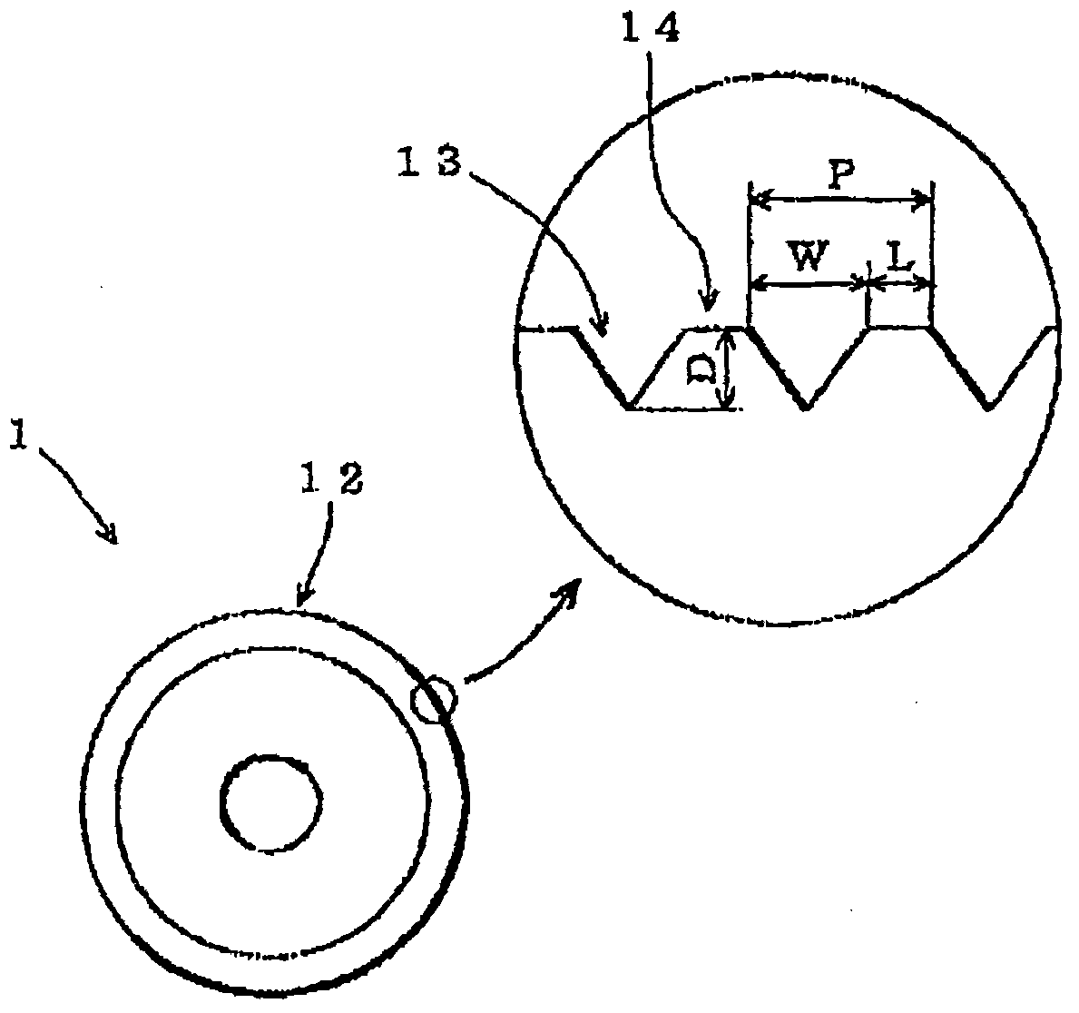
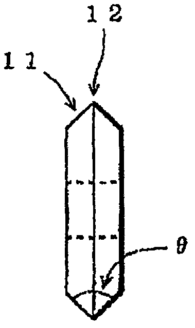
[0051] figure 1 and figure 2 One embodiment of the scribing wheel of the present invention is shown. figure 1 is the front view seen from the direction of the axis of rotation of the marking wheel, figure 2 for side view. Such as figure 2 As shown, a blade 11 having a substantially V-shaped cross section is formed on the peripheral portion of the disk-shaped wheel.

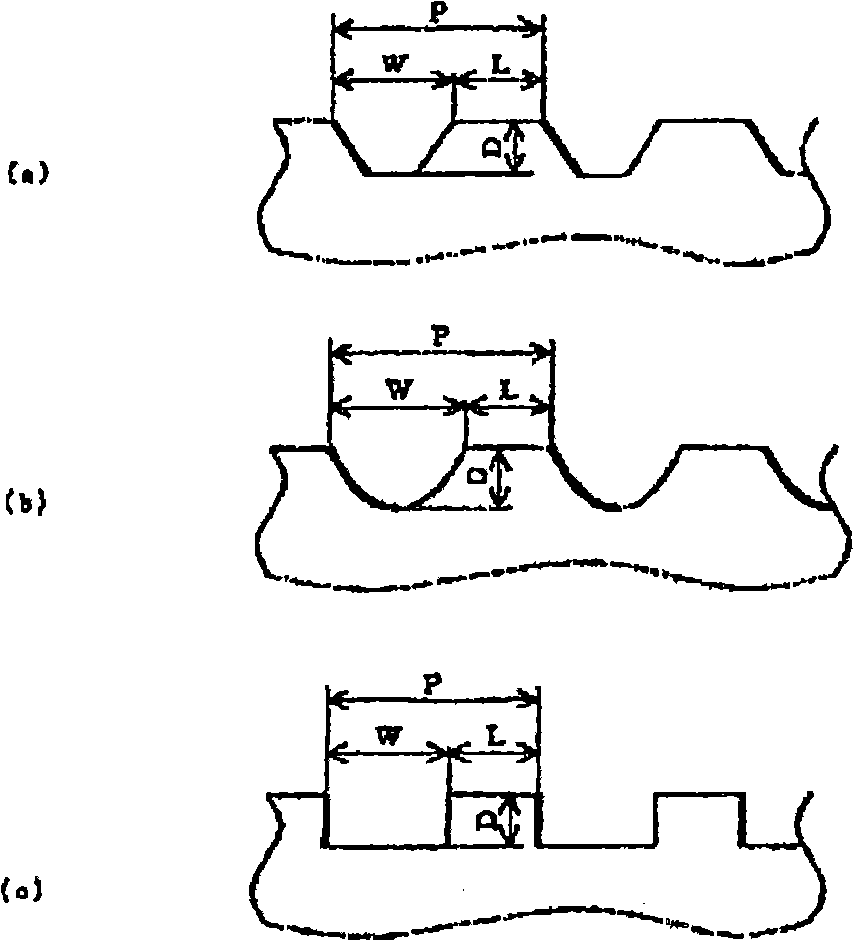
[0052] The front edge angle θ of the blade 11 is usually an obtuse angle, and the specific angle is appropriately set according to the material or thickness of the substrate to be cut, but is usually in the range of 90 to 160 degrees (for example, 100 to 140 degrees). In addition, if figure 1 As shown, a plurality of V-shaped grooves 13 are formed at predetermined intervals on the ridge line of the blade 11 , that is, the blade leading edge 12 ...


PUM

PropertyMeasurementUnit
lengthaaaaaaaaaa
distanceaaaaaaaaaa
particle sizeaaaaaaaaaa

Abstract

Provided is a scribing wheel, which has a long service life with less wearing of a blade edge and can generate a deeper vertical crack as needed, and furthermore, has less blade edge wearing even when a relatively hard substrate, such as a ceramic substrate, is scribed, and generates a vertical crack of a prescribed depth. A plurality of grooves (13) are formed at prescribed intervals on a blade edge (12), i.e., the ridge line of a wheel having an outer diameter within the range of 1 mm-5 mm. The depth (D) of the groove (13) is 25 [mu]m or more, and the length (L) of a ridge line (14) between the grooves is 25 [mu]m or more. The pitch (P) of the groove (13) is preferably within the range of 50 [mu]m-200 [mu]m.

Description

technical field [0001] The present invention relates to a scribing wheel suitable for forming scribing lines on the surface of brittle material substrates and a scribing method for forming scribing lines on the surface of brittle material substrates, in particular to a scribing wheel suitable for use on ceramic substrates (high-temperature fired ceramic multi- Scribing lines are formed on the surface of brittle materials (hard and brittle materials) such as sapphire and silicon that are harder than glass (hard and brittle materials) wheel and marking method. Background technique [0002] In recent years, LTCC substrates have attracted attention as a way to achieve higher density and miniaturization of modules. Especially for high-frequency modules of communication equipment, LTCC substrates are considered to be the best. In its manufacturing process, it is required that the productivity in the cutting process be improved and the cutting cost be reduced. [0003] The method...

Claims


Application Information

Patent Timeline
Patent Type & Authority Applications(China)
IPC IPC(8): B28D5/00B28D1/24
CPCB28D1/225Y10T83/0341Y10T83/0385Y10T225/12B28D5/0011
Inventor 留井直子冈本庆太郎富森纮
Owner MITSUBOSHI DIAMOND IND CO LTD
Why Eureka
Try Eureka