
Gear with at least two gearing stages, a linear actuator comprising such a gear and a table leg comrising such a linear actuator

A transmission device and actuator technology, which is applied in the field of raising columns, can solve problems such as power transmission and noise not being optimal, crown gear and helical gear tooth connection complex, etc.

Active Publication Date: 2011-05-11
LINAK AS
View PDF2 Cites 22 Cited by
  • Summary
  • Abstract
  • Description
  • Claims
  • Application Information

AI Technical Summary

Problems solved by technology

The transmission has proven to be good, but the tooth connections on the crown and helical gears are complex and not yet optimal in terms of power transfer and noise

Method used


Image

  • Gear with at least two gearing stages, a linear actuator comprising such a gear and a table leg comrising such a linear actuator
  • Gear with at least two gearing stages, a linear actuator comprising such a gear and a table leg comrising such a linear actuator
  • Gear with at least two gearing stages, a linear actuator comprising such a gear and a table leg comrising such a linear actuator

Examples


Embodiment Construction

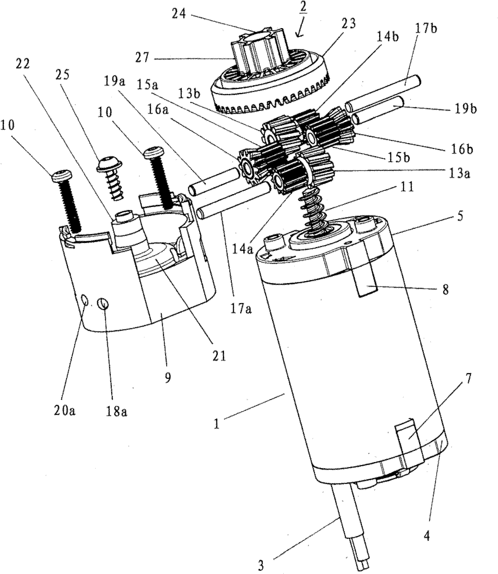
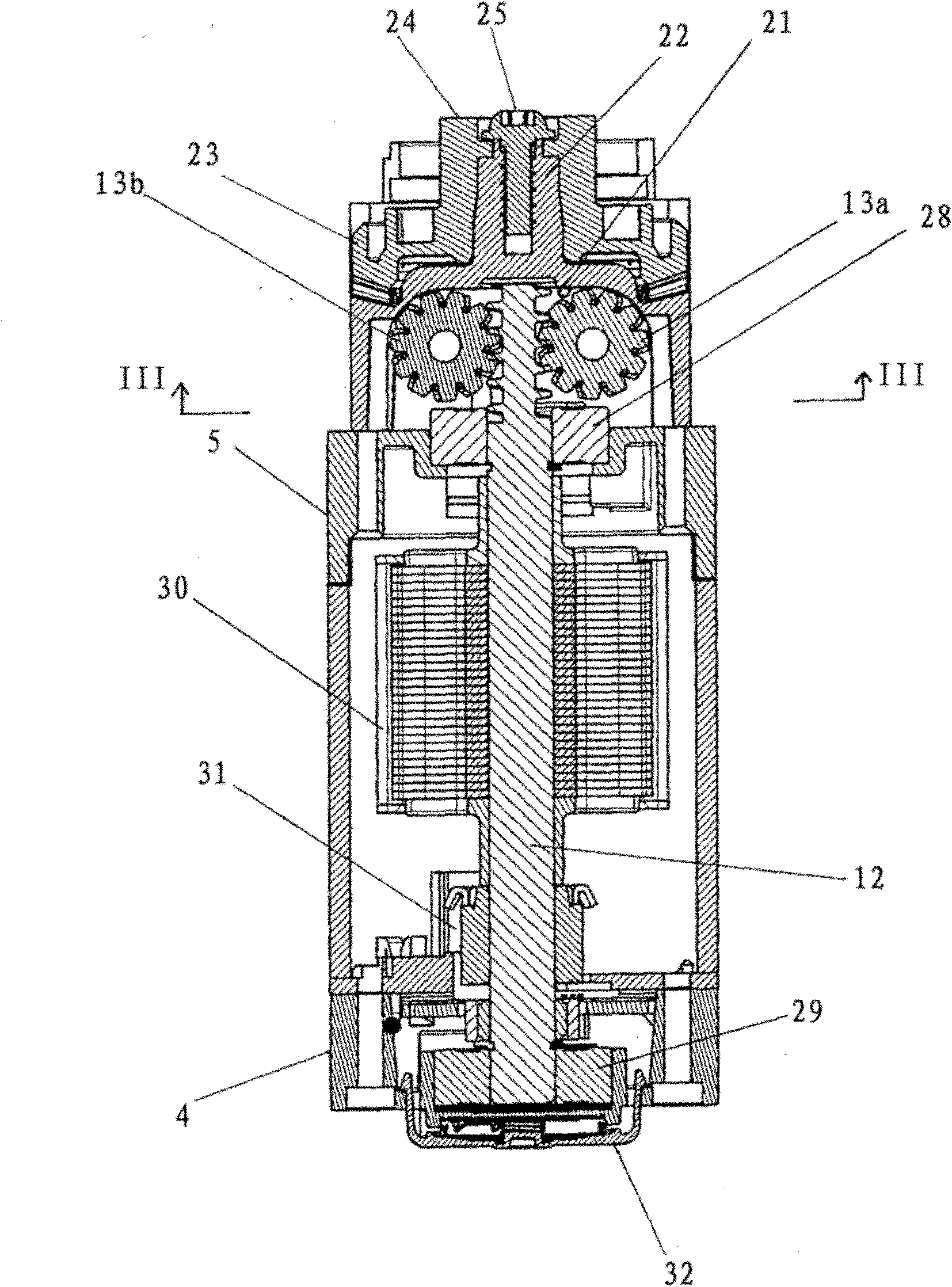
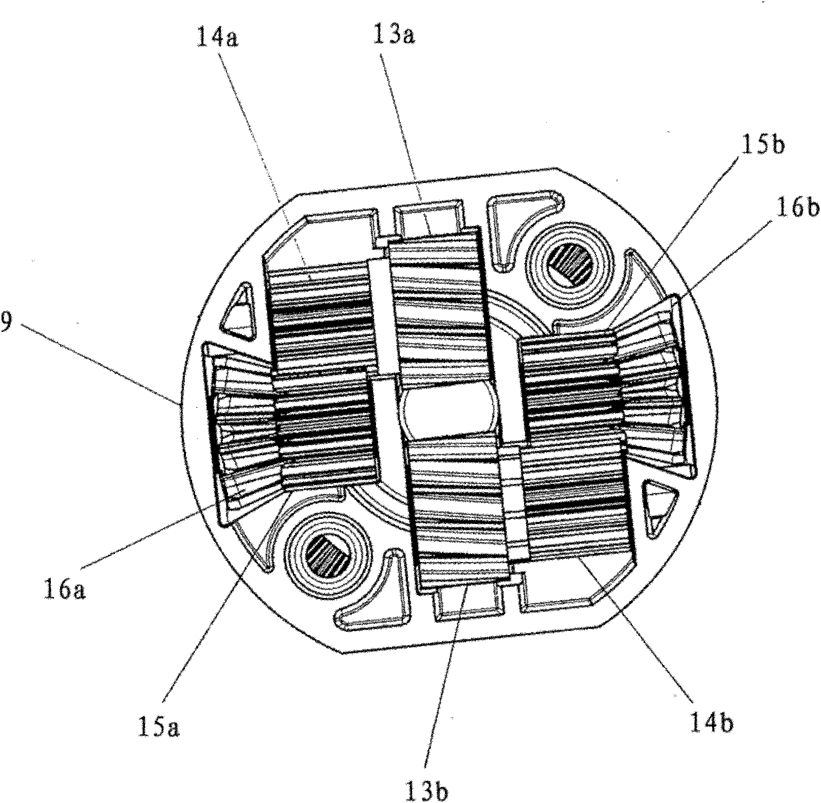
[0030] exist figure 1 An exploded view of a permanent magnet, low voltage motor 1 with an in-line front transmission 2 is shown in . The motor 1 is connected to a power source and a controller through a cable 3 . Furthermore, the motor 1 comprises a motor housing consisting of an outer cylindrical sheath and a rear cover 4 and a front cover 5 having snap locking legs 7, 8 for snapping Snaps on to the cylindrical sheath. The front transmission comprises a cylindrical transmission housing 9 which can be mounted on the front cover 5 by means of a pair of screws 10 . The transmission comprises a worm screw in the extension of the motor shaft 12 (cf. figure 2 ). The worm 11 meshes with a pair of diametrically positioned worm wheels 13a, 13b. The worm 11 is made of steel, while the worm wheels 13a, 13b are made of plastic for low noise levels. There are also spur gears 14a, 14b integral with the worm wheels 13a, 13b, which mesh with further corresponding spur gears 15a, 15b. ...


PUM


Abstract

Gear, preferably for actuators of the type, where an electric motor (1) through the gear drives an activation element, such as a pivotal arm or a longitudinally movable element, and where the gear has at least two gearing stages. The first stage is constituted by a worm drive with a worm - (11; 13a, 13b) and the subsequent gearing stage is constituted by a crown and bevel wheel (23; 16a, 16b). The crown wheel faces towards the worm drive and has a power take-off (24,27) in extension of or in all essentials in extension of the worm (11) or parallel thereto. The bevel wheel (16a, 16b) is with its axis of rotation arranged perpendicular in relation to the axis of rotation of the worm (11), and the worm wheel (13a, 13b) is in drive connection with the bevel wheel (16a, 16b) through a gear train (14a, 15a;14b;15b). Thus a relatively compact transmission with a high gearing is achieved, and by having worm wheels, toothed gearing and bevel and crown wheels of plastic the transmission is in addition silent. A good tooth mesh between bevel wheel and crown wheel is particularly important. The gear may be used in a linear actuator which again may be used in a height adjustable table leg.

Description

technical field [0001] The invention relates to a transmission as stated in the preamble of claim 1 . Furthermore, the invention relates to a linear actuator and a lifting column. Background technique [0002] EP1272778B1 to Linak A / S discloses an actuator with a transmission having two transmission stages, wherein the first stage consists of a worm drive with a worm, the subsequent transmission stage consists of Formed by a crown gear and a helical gear, wherein the helical gear is arranged in the extension of the worm wheel, the ring gear faces the worm drive, and there is a gear-shaped power take-off in the extension of the worm wheel. The patent holder Linak A / S has implemented an actuator in the shape of a rotary actuator, which is marketed as RA40. The transmission has proven to be good, but the tooth connections on the crown and helical gears are complex and not yet optimal in terms of power transmission and noise. On the other hand, the attractiveness of the trans...

Claims


Application Information

Patent Timeline
Patent Type & Authority Applications(China)
IPC IPC(8): F16H1/16F16H1/20F16H25/20
CPCA47B9/04F16H25/20F16H2025/2075F16H2025/209F16H2025/2093F16H1/225Y10T74/19665
Inventor N·克林克
Owner LINAK AS
Learn More