

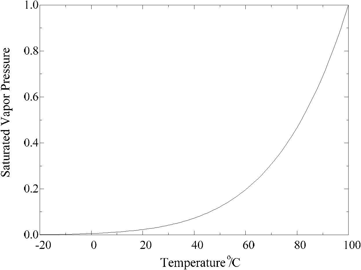
Extinguishing method and device by water-mist of preheated water
A fire extinguishing device and water mist technology, applied in fire rescue and other directions, can solve the problems of small fire calorific value, small water mist evaporation, difficulty in extinguishing small fires, etc., and achieve fast fire extinguishing speed and good fire extinguishing effect.
- Summary
- Abstract
- Description
- Claims
- Application Information
AI Technical Summary
Problems solved by technology
Method used
Image

Examples
Embodiment 1
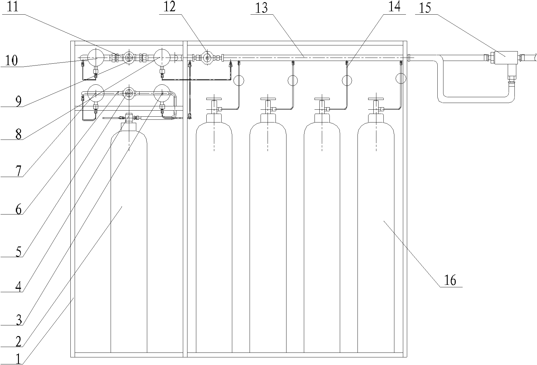
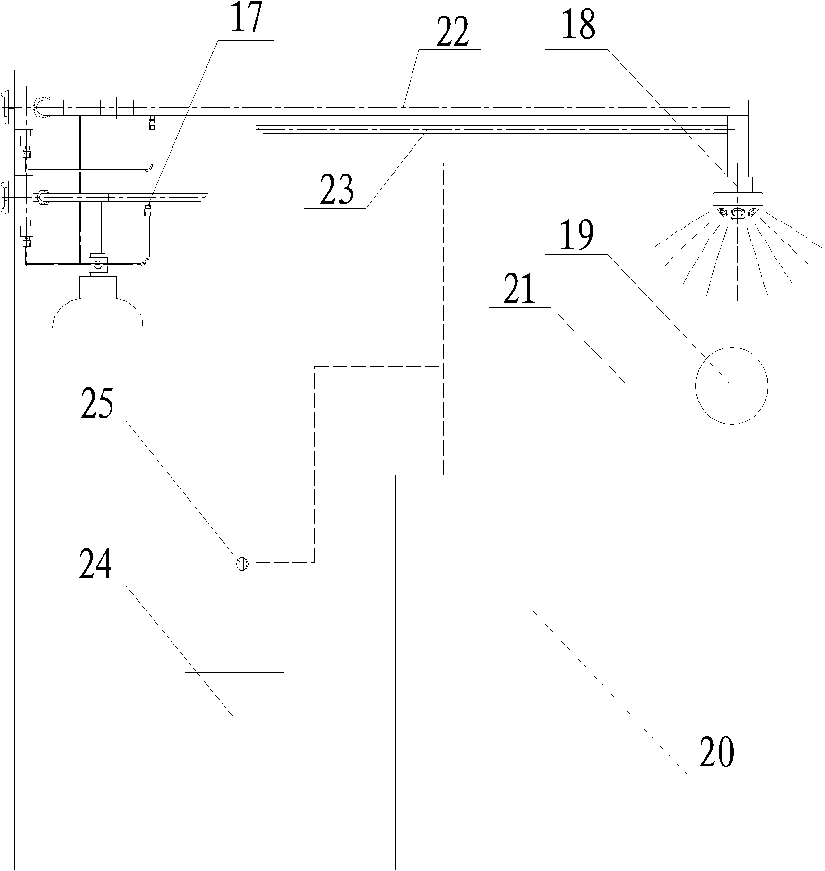
[0050] Embodiment 1. Add a heating device in the water mist fire extinguishing device;
[0051] The composition and structure of the system are as Figure 2A , 2B As shown, the system consists of cabinet 1, pressure water bottle 2, water bottle pressure indicator 3, bottle head interface 4, emergency manual water valve 5, waterway solenoid valve 6, waterway pressure indicator 7, high pressure fire extinguishing gas fire extinguishing agent bottle group pressure indicator Table 8, emergency manual gas valve 9, gas path pressure indicator 10, gas path solenoid valve 11, high pressure gas path pressure reducer 12, high pressure gas bus bar 13, high pressure gas pipeline 14, swirl atomizing mixer 15 , high-pressure gas fire extinguishing agent bottle group 16, water filter 17, Laval two-phase flow ultra-fine gas water mist nozzle 18, fire detector 19, fire control alarm 20, cable 21, gas fire extinguishing agent pipeline 22, water pipeline 23, electric heater 24, pressure switch...
Embodiment 2
[0057] Embodiment 2. The typical application of heating device installed in the pressure water bottle
[0058] The preheating of water is carried out directly in the pressure water bottle. The present invention provides an example of hydroelectric heating in the pressure water bottle. The pressure water bottle adopts the structure and principle of a domestic electric water heater. Such as image 3 As shown, this embodiment is composed of a bottle head valve 201 , an insulating layer 202 , a temperature control system 203 , a pressure bottle body 204 and an electric heater 205 . The electric heater 205 is located inside the pressure bottle body 204, the temperature control system 203 is located at the head of the pressure bottle body 204, the temperature control system 203 is connected to the bottle head valve 201 and the electric heater 205, and the insulation layer 2 is close to the inside of the pressure bottle body 204 . This temperature control system controls the power ...
Embodiment 3
[0059] Embodiment 3. A typical application of installing a heating device in a two-phase flow ultra-fine gas-water mist nozzle
[0060] Install electric heating elements on the conventional fine water mist nozzle and the water supply pipe close to the nozzle, and select the power of the electric heating element according to the nozzle flow and preheating temperature. Such as Figure 4 , 6 As shown, the two-phase flow ultra-fine air-water mist nozzle of the embodiment of the present invention is composed of three parts: a water supply pipe 301, an electric heating element 302 and a Laval nozzle 303. The specific structure can be varied. Generally, the electric heating element is installed on the nozzle 18 Or be installed on the water supply pipe 301.
[0061] The working process of the nozzle is as follows: when the nozzle is not working, the electric heating element 302 is not energized. The component is powered off. Whether there is fine water mist sprayed out and the flo...
PUM
 Abstract
Description
Claims
Application Information