System for realizing life cycle model of plate blank in basic automation

A basic automation and life cycle technology, which is applied in the system field of realizing the slab life cycle model, can solve the problems that the actual pulling speed in the cooling area cannot be accurately obtained by the frequency converter, the target flow rate in the cooling area is inaccurate, and the speed is reduced to achieve the solution goal The problem of accurate flow control, improving the accuracy of target flow control, and avoiding the effect of time lag

Active Publication Date: 2011-05-18
SHANGHAI BAOSIGHT SOFTWARE CO LTD
View PDF3 Cites 8 Cited by
  • Summary
  • Abstract
  • Description
  • Claims
  • Application Information

AI Technical Summary

Problems solved by technology

[0004] 2. Unstable casting speed in the process of pouring and tailing
During the pouring process and the tail drawing process, the casting speed will change according to the speed curve pre-stored in the PLC (programmable controller) or the operator will artificially control the casting speed, causing the deviation between the actual casting speed and the electrical casting speed in the cooling zone larger
[0005] 3. Sudden changes in casting speed during pouring
Due to changes in various site conditions, such as equipment failure or defects (such as steel breakout prediction, etc.), the casting speed will be automatically or manually reduced, resulting in a large deviation between the actual casting speed and the electrical casting speed in the cooling zone
According to the data collected so far, there is at least a time lag of 2 second

Method used


Image

  • System for realizing life cycle model of plate blank in basic automation
  • System for realizing life cycle model of plate blank in basic automation
  • System for realizing life cycle model of plate blank in basic automation

Examples


Embodiment Construction

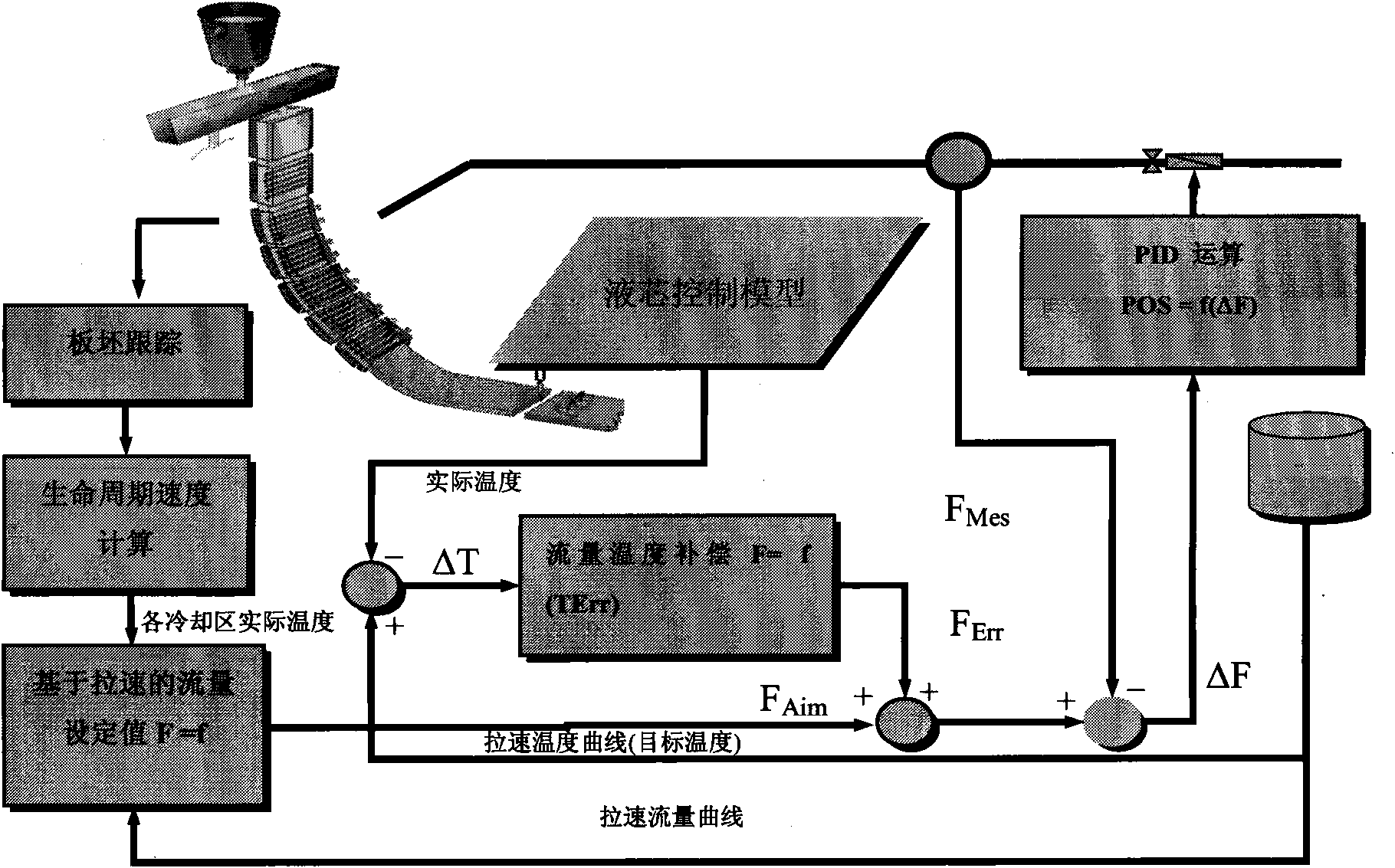
[0029] see figure 1 As shown, in an embodiment of the present invention, the system for implementing the slab life cycle model in basic automation includes:

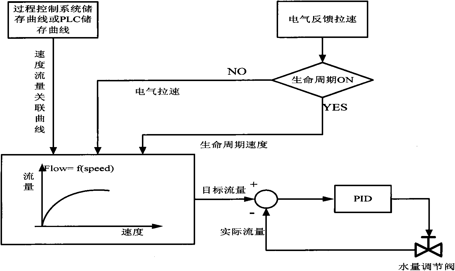
[0030] The slab tracking module dynamically tracks the heat flow slices, and divides the heat flow into N (N is an integer greater than 1) cooling zones (or cooling loops) according to mechanical and process design, and each cooling zone is further divided into M (M is an integer greater than 1) slices with a length of 100mm, and the time when each slice is poured out of the crystallizer is stored in the time queue data block (combined with Figure 4 shown) and move forward with the slice (because of pouring), until the slice is out of the casting machine.

[0031] The time queue structure for each cooling circuit PLC to track slices is as follows: Figure 4 as shown ( Figure 4 Middle V 1 , V 2 , Vn respectively represent the actual speed of cooling circuit 1, the actual speed of cooling circuit 2, and the actual s...


PUM

PropertyMeasurementUnit
Lengthaaaaaaaaaa

Abstract

The invention discloses a system for realizing a life cycle model of a plate blank in basic automation, which comprises a plate blank tracking module, a life cycle speed calculating module, a casting speed-based flow set value module, a casting speed flow curve on-line optimizing module and a flow temperature compensation module, wherein the plate blank tracking module tracks heat flow slices dynamically; the life cycle speed calculating module records the time when each cooling loop slice comes out of a crystallizer; the casting speed-based flow set value module adjusts the cooling target flow of each cooling area dynamically according to the dynamic change of casting speed in the pouring process; the casting speed flow curve on-line optimizing module optimizes a cooling area casting speed curve and a cooling area flow curve on line and modifies the target flow of cooling loops at different casting speeds by a human-computer interface; and the flow temperature compensation module controls proportion integration differentiation (PID) water volume compensation according to temperature deviation, and optimizes cooling water volume according to target temperature. The system can overcome the control deviation of the target flow in the cooling areas due to the sudden change of the casting speed in the pouring process, improve the control accuracy of the target flow in the cooling areas, and reflect the actual casting speed condition on site in real time.

Description

technical field [0001] The invention relates to the field of medium-thick plate rolling in the metallurgical industry, in particular to a system for controlling the secondary cooling flow rate of slab continuous casting and realizing a slab life cycle model in basic automation. Background technique [0002] In the continuous casting production process of plate rolling, the pulling speed is generally referred to as the electrical pulling speed, that is, the average pulling speed fed back by the frequency converter of each pinch roll (or pulling and straightening roll) (here referred to as the electrical pulling speed, The same below). There is a large deviation between the electrical pulling speed and the actual casting direction moving speed of each cooling zone of continuous casting (here referred to as the actual pulling speed of the cooling zone, the same below). The reasons for the large deviation between the electrical pulling speed and the actual cooling speed of each...

Claims


Application Information

Patent Timeline
IPC IPC(8): B22D11/22
Inventor 徐永军黄君陈在根
Owner SHANGHAI BAOSIGHT SOFTWARE CO LTD
Why Eureka
Try Eureka