
Irradiation method of LED

A reflection area and horizontal direction technology, applied in the field of LED irradiation, can solve problems such as glare easily, and achieve the effects of improving light source utilization, improving user experience, and saving resources

Inactive Publication Date: 2011-05-18
王默文
View PDF0 Cites 0 Cited by
  • Summary
  • Abstract
  • Description
  • Claims
  • Application Information

AI Technical Summary

Problems solved by technology

[0005] The technical problem to be solved by the present invention is to provide an LED irradiation method, which solves the problem of glare easily generated by current LED lamps

Method used


Image

  • Irradiation method of LED
  • Irradiation method of LED
  • Irradiation method of LED

Examples


Embodiment Construction

[0022] The present invention will be further described below in conjunction with the accompanying drawings and specific embodiments.

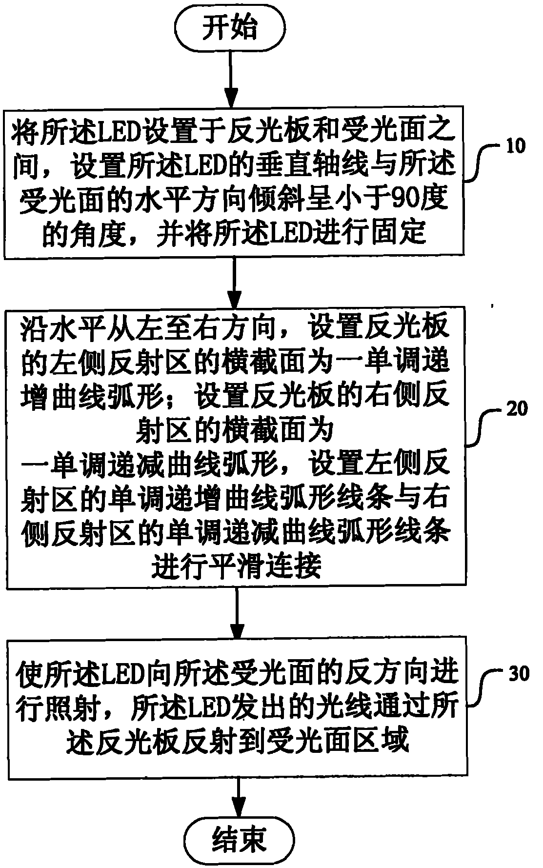
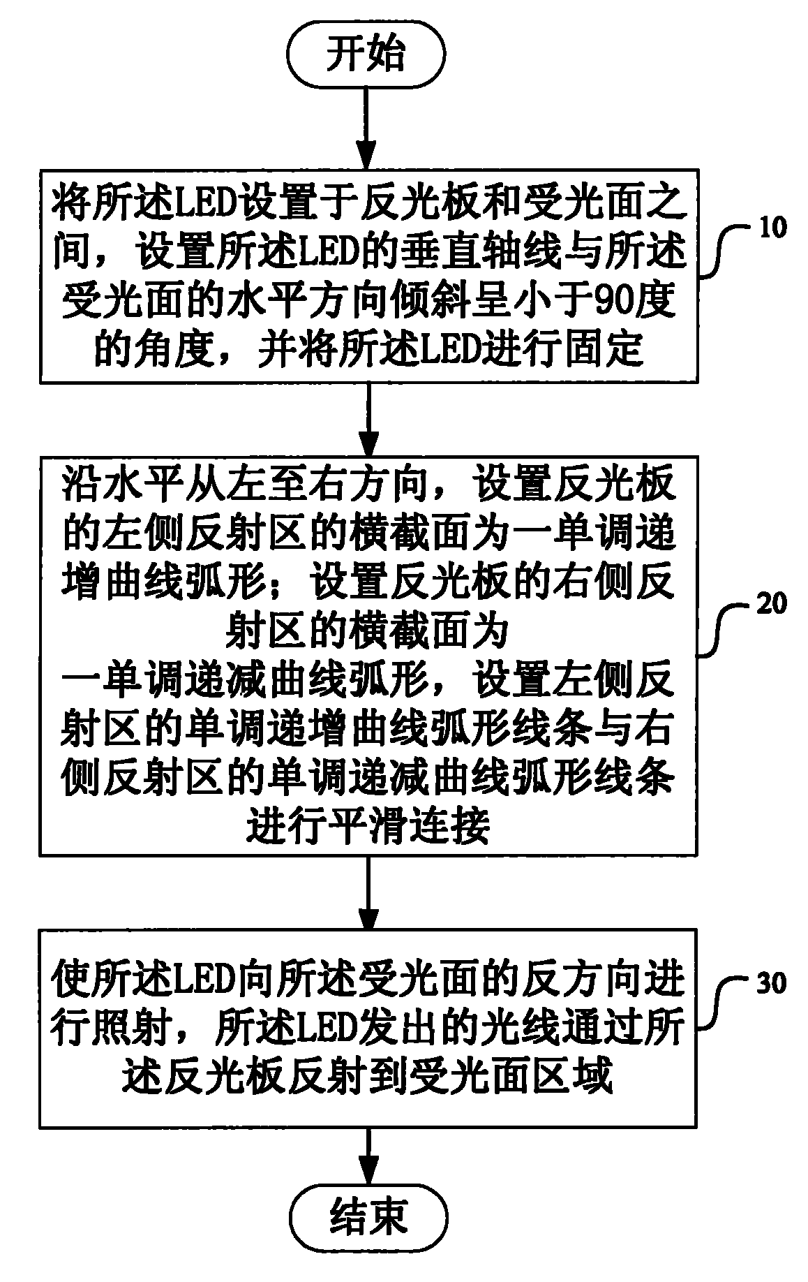
[0023] like figure 1 Shown, the illumination method of a kind of LED of the present invention comprises the following steps:

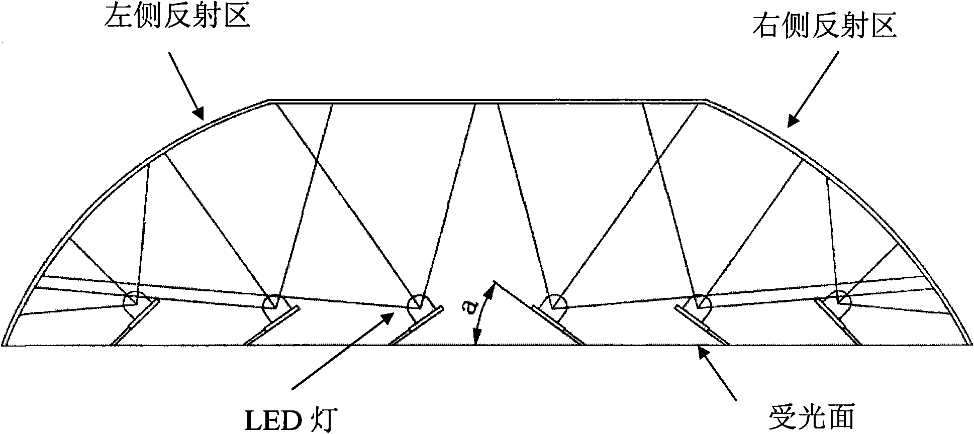
[0024] Step 10, disposing the LED between the reflector and the light-receiving surface, setting the vertical axis of the LED to be inclined at an angle less than 90 degrees to the horizontal direction of the light-receiving surface, and fixing the LED;

[0025] Said setting said LED between the reflective plate and the light-receiving surface means:

[0026] A plurality of LEDs are arranged between the reflective plate and the light-receiving surface, and the LEDs are arranged horizontally and uniformly.

[0027] The setting that the vertical axis of the LED is inclined at an angle less than 90 degrees to the horizontal direction of the light-receiving surface means:

[0028] Take the midpoint of a straight line for...


PUM


Abstract

The invention discloses an irradiation method of an LED, which comprises the following steps: arranging an LED between a reflector and a light receiving surface, arranging an angle between the vertical axis of the LED and the horizontal direction of the light receiving surface to be less than 90 degrees, and fixing the LED; arranging the cross section of a left reflecting area of the reflector to be a monotonically increasing curve arc horizontally from left to right; arranging a cross section of a right reflecting area of the reflector to be a monotonically decreasing curve arc; and enabling the LED to irradiate toward the opposite direction of the light receiving surface, wherein the lights emitted by the LED are reflected to the light receiving surface area through the reflector. By adopting the irradiation method disclosed by the invention, the problem that glare is often generated by the irradiation of current LED lamp is solved, the light utilization rate of the LED lamp is increased, the resources are saved, and the using experience of users is improved.

Description

technical field [0001] The invention relates to the field of lamps, in particular to an LED irradiation method. Background technique [0002] The so-called LED lamps, as the name suggests, refer to lamp products that use LED (Light-emitting Diode, light-emitting diode) technology as the main light-emitting source. LED is a solid-state semiconductor component, which uses current to flow forward to the semiconductor p-n junction coupling, and then the negatively charged electrons and positively charged holes separated in the semiconductor are combined with each other to generate photons. Emission, different types of LEDs can emit light of different wavelengths from infrared to blue, and from violet to ultraviolet. [0003] At present, LEDs have been widely used, but LED lamps are prone to glare when lighting, which makes users uncomfortable during use. [0004] Therefore, it is currently necessary to provide a new technical solution for LED illumination to solve the above pr...

Claims


Application Information

Patent Timeline
IPC IPC(8): F21V7/04F21V19/00F21V7/09F21Y101/02
Inventor 王默文
Owner 王默文
Learn More