
Flat top effect estimation method for near-field radar scattering cross section of rectangular flat plate

A technology of radar cross-section and flat plate, which is applied in the field of electromagnetic compatibility research, and can solve the problems that cannot be estimated

Active Publication Date: 2011-05-18
CHINA SHIP DEV & DESIGN CENT
View PDF1 Cites 6 Cited by
  • Summary
  • Abstract
  • Description
  • Claims
  • Application Information

AI Technical Summary

Problems solved by technology

Therefore, the flat-top "width" of this effect cannot be estimated by traditional far-field RCS methods

Method used


Image

  • Flat top effect estimation method for near-field radar scattering cross section of rectangular flat plate
  • Flat top effect estimation method for near-field radar scattering cross section of rectangular flat plate
  • Flat top effect estimation method for near-field radar scattering cross section of rectangular flat plate

Examples


Embodiment Construction

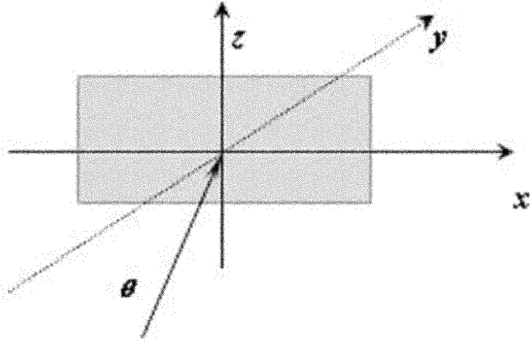
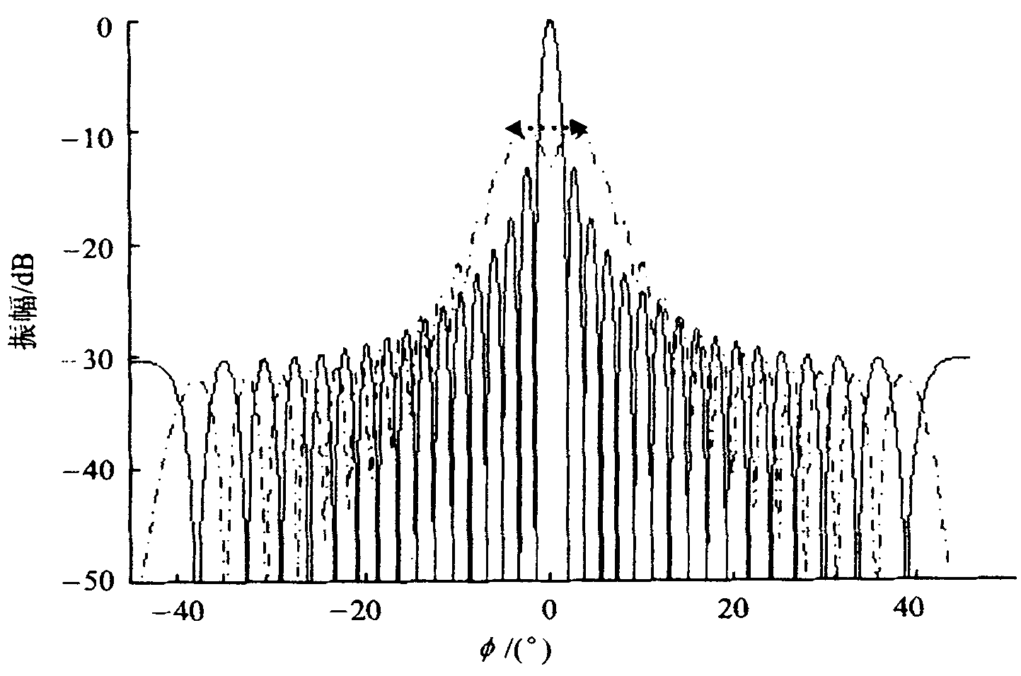
[0017] figure 1 It is a schematic diagram of a rectangular plate. The rectangular plate is located in the x-z plane. The angle between the incident wave of the radiation source and the normal y is θ. There is a significant "flat top" effect in the near-field RCS results of the normal incidence condition of the rectangular plate target ,Such as figure 2 shown.

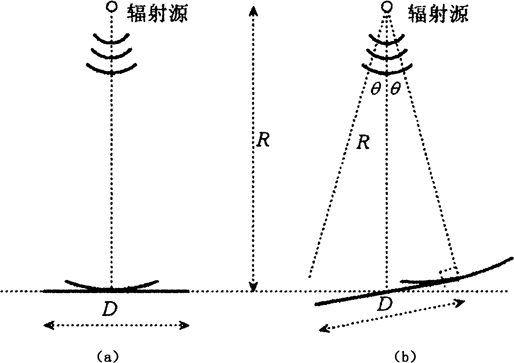
[0018] Suppose a radiation source emits a spherical wave to a rectangular plate with a length D, and the distance from the radiation source to the midpoint of the rectangular plate is R. When the incident wave direction is perpendicular to the end point of the rectangular plate, it is the critical state of the “flat-top” effect, and the critical state is established geometric model, such as image 3 shown.

[0019] image 3 Represents an ideal spherical wave point source illuminating a rectangular plate along the normal direction in the near-field region. image 3 (a) is the state when the spherical wave is normal...


PUM


Abstract

The invention provides a flat top effect estimation method for a near-field radar scattering cross section of a rectangular flat plate. A critical state is reached when the included angle between a connecting line from a radiation source to one end point of the rectangular flat plate and the rectangular flat plate is 90 degrees, and the included angle between the connecting line from the radiation source to the end point of the rectangular flat plate and an R is a critical incident angle Theta, wherein the critical incident angle Theta is equal to arcsin (D / 2R), D is the length of the flat plate and R is the vertical distance from the radiation source to the flat plate, and the width M of the flat top is quantificationally estimated to be twice the corresponding critical incident angle Theta according to a geometric relationship. The invention provides a simple method for estimating the width of the flat top of the near-field RCS (Radar Cross Section), the width of flat top of the near-field RCS is quantificatioinally estimated from the point of the geometric relationship, the blind spot of the field is solved, and the obtained conclusion is more accurate. Moreover, by virtue of the method, a favorable ground is provided for analyzing the near-field scattering flat top phenomenon of the flat plate and a building thereof, and the method is good for the prediction and the analysis on the near-field RCS of various targets with a similar flat plate structure.

Description

technical field [0001] The invention belongs to the field of electromagnetic compatibility research. Background technique [0002] Normal incidence conditions on a rectangular flat target (such as figure 1 There is a significant "flat-top" effect in the near-field radar cross section (RCS) results shown in ), that is, the maximum value of the RCS curve is not a sharp peak but a relatively flat flat top (such as figure 2 shown, the "flat-top" range covered by the arrow). From the existing research results, it is found that the "width" of the flat top, that is, the angle range corresponding to the flat top varies, and is related to parameters such as the size of the rectangular flat plate, the distance between the target and the radiation source, and so on. Since the near-field RCS of the target is different from the traditional far-field RCS, the electromagnetic wave radiated by the radiation source can no longer be assumed to be a plane wave, but should be a spherical wav...

Claims


Application Information

Patent Timeline
IPC IPC(8): G01S7/41
Inventor 方重华黄琼谭辉温定娥刘其凤
Owner CHINA SHIP DEV & DESIGN CENT
Learn More