Generating circuit and detecting method of pulse width modulation (PWM) signals

A PWM signal and circuit generation technology, applied in the field of communication, can solve the problems of complex generation circuit structure and cumbersome detection method, and achieve the effects of simple method, high achievability and simplified circuit.

Inactive Publication Date: 2011-05-18
SHANGHAI DIANJI UNIV
View PDF1 Cites 3 Cited by
  • Summary
  • Abstract
  • Description
  • Claims
  • Application Information

AI Technical Summary

Problems solved by technology

[0009] The present invention aims to provide a novel generation circuit and detection method for PWM signals aiming at defects such as complex structure and cumbersome detection methods of the existing PWM signal generation circuit in the prior art.

Method used


Image

  • Generating circuit and detecting method of pulse width modulation (PWM) signals
  • Generating circuit and detecting method of pulse width modulation (PWM) signals
  • Generating circuit and detecting method of pulse width modulation (PWM) signals

Examples


Embodiment Construction

[0019] In order to illustrate the technical content, structural features, achieved goals and effects of the present invention in detail, the following will be described in detail in conjunction with the embodiments and accompanying drawings.

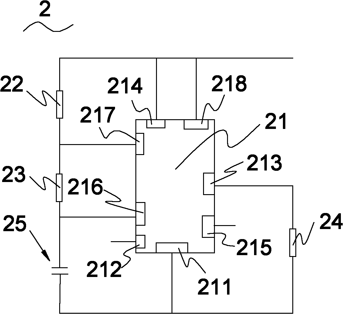
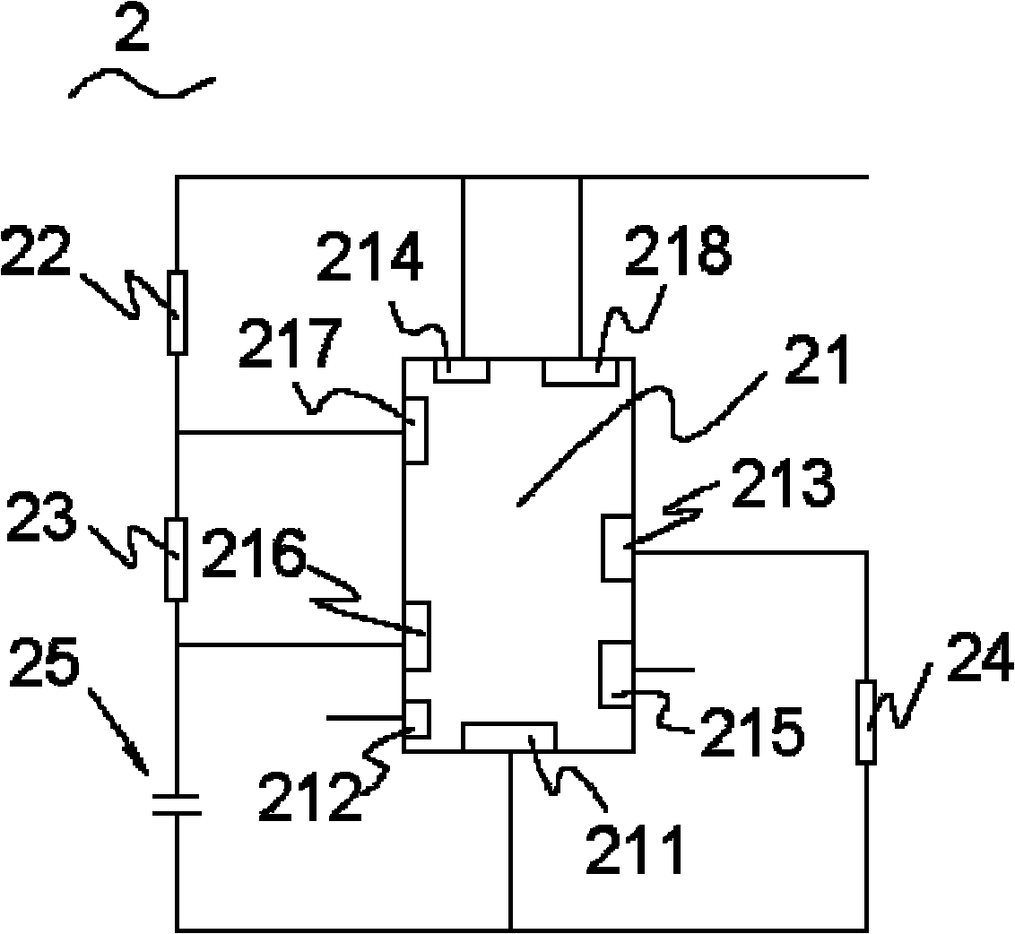
[0020] see figure 2 , figure 2 Shown is a schematic structural diagram of the pulse width modulation oscillator circuit 2 . The pulse width modulation oscillator circuit 2 is a monostable circuit composed of a 555 timer 21 externally connected with a first resistor 22 , a second resistor 23 , a third resistor 24 , and a capacitive element 25 . The 555 timer 21 has 8 terminal pins, which are respectively defined as the first terminal pin 211, the second terminal pin 212, the third terminal pin 213, the fourth terminal pin 214, the fifth terminal pin 215, and the sixth terminal pin 216 , the seventh terminal pin 217, and the eighth terminal pin 218. Wherein, the fifth terminal pin 215 is a voltage control terminal. The seventh end pi...


PUM


Abstract

The invention provides a generating circuit of pulse width modulation (PWM) signals. The generating circuit comprises a PWM oscillator circuit, wherein the PWM oscillator circuit further comprises a 555 timer, a first resistor, a second resistor, a third resistor and a capacitor element; the 555 timer is provided with a plurality of pins; each pin comprises an analog signal input end, a modulating signal input end and an output signal output end; and the three resistors and the capacitor element are all externally connected with the 555 timer. A detecting method of the PWM signals generated by the generating circuit is characterized by adopting a low-pass filter or an envelope detection method to demodulate the signals. The invention has the following beneficial effects: by adopting the 555 timer to form the generating circuit of the PWM signals, not only the method is simple, the circuit is simplified and the realizability is high, but also ideal demodulation of different types and frequencies of signals can be realized by adopting the low-pass filter.

Description

technical field [0001] The invention relates to the communication field, in particular to a generation circuit and a detection method of a PWM signal. Background technique [0002] In modern communications, digital circuits are widely used, and digital signal processing technology is also developing accordingly. In reality, most information and messages are analog signals. In actual signal processing and information transmission, these analog signals must first be converted into digital signals to form digital baseband signals. [0003] The more common modulation methods of digital baseband signals include pulse amplitude modulation (PAM), pulse code modulation (PCM), incremental pulse code modulation (DPCM), delta modulation (DM), and time modulation (PTM). Among them, pulse time modulation (PTM) includes pulse width modulation (PWM) and pulse position modulation (PPM). The pulse position modulation PPM signal is easily obtained from the pulse width modulation PWM signal...

Claims


Application Information

Patent Timeline
Patent Type & Authority Applications(China)
IPC IPC(8): H04B17/00H04B14/04H03K7/08
Inventor 胡之惠杨宇陈布雨陈智鹏李渊
Owner SHANGHAI DIANJI UNIV
Why Eureka
Try Eureka