
Driving device for light emitting diode backlight

A technology of light-emitting diodes and driving devices, which is applied in the field of backlight driving, can solve problems such as difficulty in communication and control of LED controllers, difficulty in circuit layout, and increased cost of LED controllers. It achieves simple driving control methods, reduces voltage ripples, The effect of reducing the amount used

Inactive Publication Date: 2011-05-18
TOP VICTORY INVESTMENTS
View PDF6 Cites 24 Cited by
  • Summary
  • Abstract
  • Description
  • Claims
  • Application Information

AI Technical Summary

Problems solved by technology

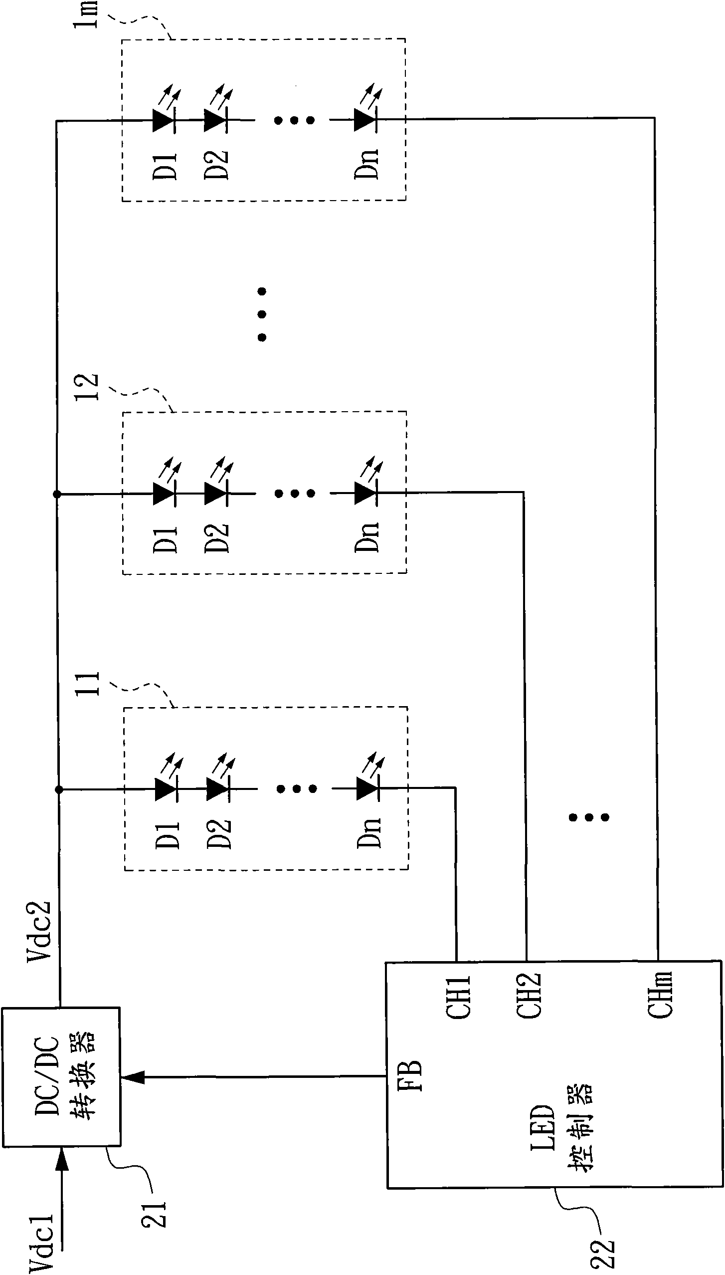
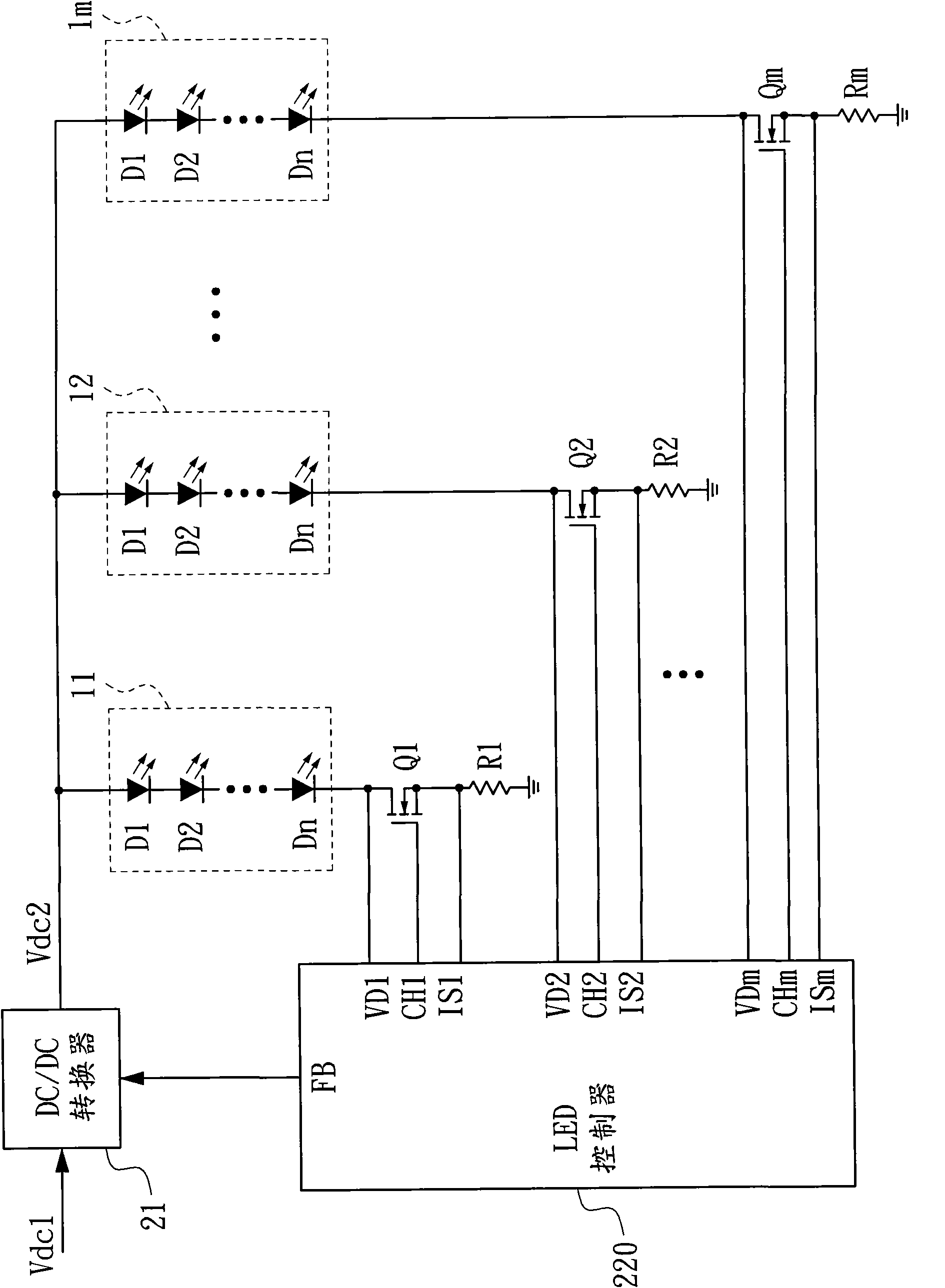
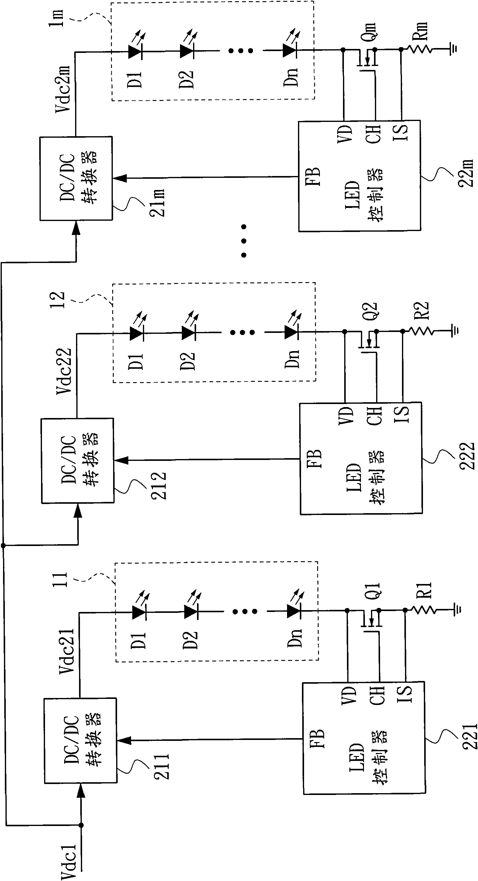
Moreover, with the increase in the number of lamp strings 11-1m of the LED backlight, for figure 2 For the driving device of the LED backlight shown, the number of pins of the LED controller 220 and the number of additional transistors Qi and resistors Ri will all increase, making the circuit layout difficult and increasing the cost. image 3 For the driving device of the LED backlight shown, the number of DC / DC converters 211-21m, LED controllers 221-22m, and additional transistors Qi and resistors Ri will all increase, in addition to making the circuit layout difficult and increasing the cost In addition, the communication and control among the LED controllers 221-22m will be difficult due to the increase in the number of LED controllers

Method used


Image

  • Driving device for light emitting diode backlight
  • Driving device for light emitting diode backlight
  • Driving device for light emitting diode backlight

Examples


Embodiment Construction

[0058] In order to make the object, technical solution and advantages of the present invention clearer, the implementation manner of the present invention will be further described in detail below in conjunction with the accompanying drawings.

[0059] Figure 4 It is a circuit diagram of a driving device for an LED backlight according to a preferred embodiment of the present invention. Please refer to Figure 4 , the LED backlight source includes a plurality of first light strings 311-31m and a plurality of second light strings 321-32m, and each of the first light strings 31i and each of the second light strings 32j includes a plurality of light-emitting diodes coupled in series D1 to Dn, wherein m and n are both positive integers, i is any positive integer from 1 to m, and j is any positive integer from 1 to m. The driving device of the LED backlight source includes a first current mirror 41 , a second current mirror 42 , a control circuit 43 and a DC / DC converter 44 .

...


PUM


Abstract

The invention discloses a driving device for light emitting diode (LED) backlight, and belongs to the technical field of backlight drive. The LED backlight is divided with a first light string group and a second light string group for time division control. The driving device comprises a first current mirror, a second current mirror and a control circuit. The enabled first current mirror balances the current of each first light string, and the enabled second current mirror balances the current of each second light string. The control circuit disables the second current mirror in a first period and adjusts the enabled time length of the first current mirror according to the dimming signals and the total current of the first light strings, and disables the first current mirror in a second period and adjusts the enabled time length of the second current mirror according to the dimming signals and the total current of the second light strings; therefore, only one light string group is driven to emit light in each period.

Description

technical field [0001] The invention relates to the technical field of backlight driving, in particular to a driving device for a light emitting diode backlight. Background technique [0002] Existing liquid crystal displays generally use cold cathode fluorescent lamps (Cold Cathode Fluorescent Lamp, CCFL for short) or light-emitting diodes (Light-Emitting Diode, LED for short) as a backlight source. However, due to the increasingly serious global warming phenomenon, countries are increasingly strict on the power consumption of consumer electronics products, making CCFL backlights gradually replaced by LED backlights due to their high power consumption. [0003] figure 1 It is a circuit diagram of an existing LED backlight driving device. Please refer to figure 1 , the LED backlight source includes m light strings 11-1m, and each light string 1i includes n light-emitting diodes D1-Dn coupled in series, where m and n are both positive integers, and i is any positive number...

Claims


Application Information

Patent Timeline
IPC IPC(8): H05B37/02G09G3/36
CPCY02B20/42Y02B20/40
Inventor 李振强李吉欣林立韦林文明廖俊期
Owner TOP VICTORY INVESTMENTS
Learn More