Tin soldering system of automatic tin soldering robot

A robot and automatic welding technology, which is applied in the direction of welding/welding/cutting objects, tin feeding devices, welding equipment, etc., can solve problems such as difficult to control precise travel, wear and tear, and affect the service life of welding equipment, so as to prolong the service life and reduce the wear, avoid the effect of frequent up and down movements

Active Publication Date: 2011-05-25
CHANGZHOU MINGSEAL ROBOT TECH CO LTD
View PDF1 Cites 23 Cited by
  • Summary
  • Abstract
  • Description
  • Claims
  • Application Information

AI Technical Summary

Problems solved by technology

At the same time, there is an obvious defect in the above two kinds of soldering equipment: when the soldering iron head moves to the soldering working position for soldering, it will rise to move to the next soldering working position, so when performing a large number of soldering at the same horizontal working position , the soldering iron head still needs to be driven by the universal arm or the up and down movement mechanism, so that on the one hand, it is difficult to control the small travel distance accurately, on the other hand, the frequent movement of the universal arm or the up and down movement mechanism is easy to cause wear and affect the service life of the welding equipment

Method used


Image

  • Tin soldering system of automatic tin soldering robot
  • Tin soldering system of automatic tin soldering robot
  • Tin soldering system of automatic tin soldering robot

Examples


Embodiment 1

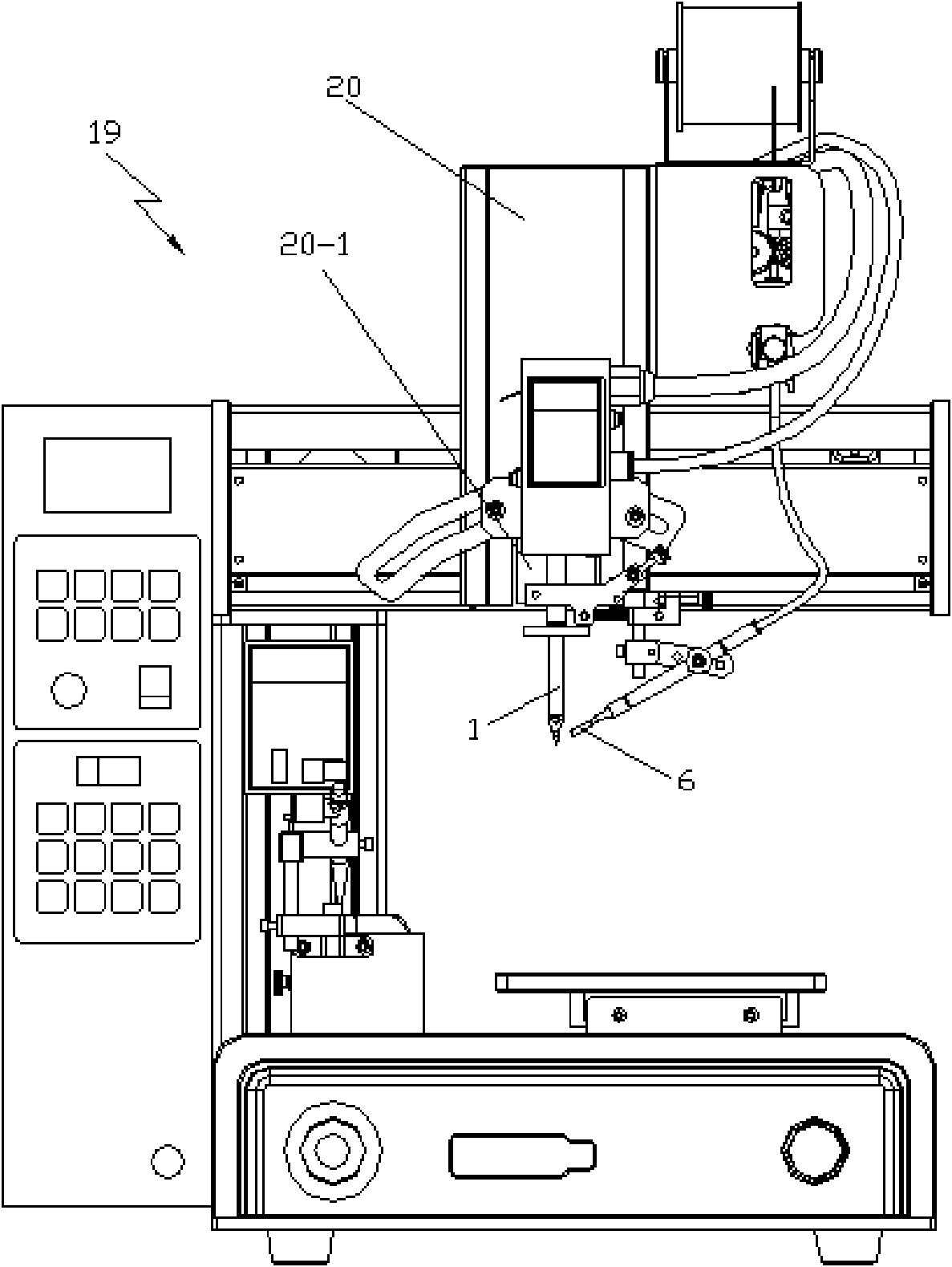
[0033] See figure 1 , the soldering iron tip movement mechanism of the soldering system of the automatic soldering robot of this embodiment is fixed on the Z-axis module 20 of the automatic soldering robot 19 that controls the movement in the up and down direction through the Z-axis connecting block 20-1, and the tin wire precise positioning mechanism is fixed on the soldering iron the upper end of head 1.

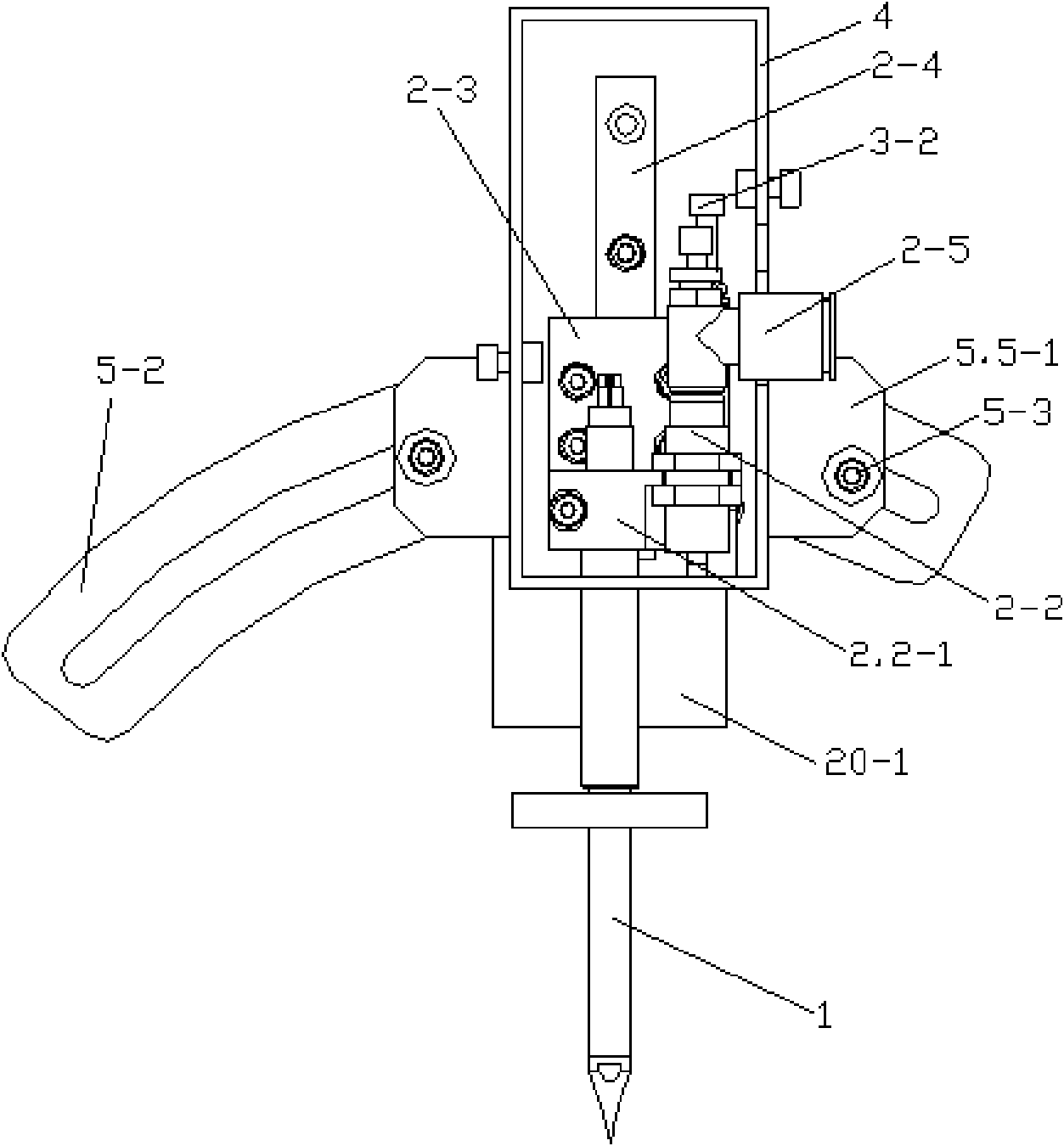
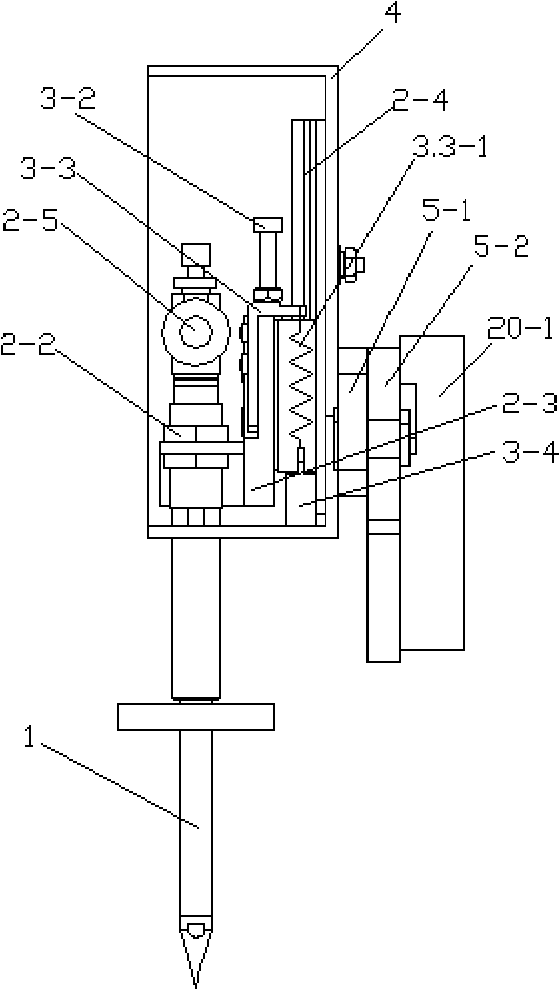
[0034] See Figure 2 to Figure 4 , The soldering iron tip movement mechanism of the soldering system of the automatic soldering robot includes a soldering iron tip 1, a moving device 2, a pressure regulating device 3, a box body 4 and an angle regulating device 5. The moving device 2 and the pressure regulating device 3 are arranged in the box body 4 .

[0035] The mobile device 2 includes a connecting block 2-1, a cylinder 2-2, a slide plate 2-3, a linear slide rail 2-4 and a speed regulating joint 2-5. The connection block 2-1 connects the upper end of the soldering i...


PUM


Abstract

The invention discloses a tin soldering system of an automatic tin soldering robot, which comprises a soldering bit, a soldering bit moving mechanism and a tin wire accurate positioning mechanism, wherein the soldering bit moving mechanism comprises a moving device connected with the soldering bit; the moving device comprises a connecting block, an air cylinder, a sliding plate and a linear sliding rail; the upper end of the soldering bit and the cylinder body of the air cylinder are connected together by the connecting block, and the connecting block is also connected with the sliding plate; the sliding plate is in sliding connection with the linear sliding rail; a tin wire guide nozzle of the tin wire accurate positioning mechanism is connected with the connecting block through a connecting rod, the connecting block is connected with a connecting shaft, a deflection block is fixedly connected with the connecting shaft, the connecting shaft is connected with a pitching block in a rotating mode, the pitching block is connected with a clamping block, the clamping block is fixed on the upper end of the soldering bit, a horizontal adjustment screw is connected with the deflection block in a rotating mode, and the front end of the horizontal adjustment screw is connected with the pitching block in a sliding mode. The invention can reduce the abrasion of a mechanism which drives the soldering bit to move up and down, ensures the precision of the repeating motion of the soldering bit in tin soldering, and can enable transported tin wires accurately to be positioned to a tin soldering point of the soldering bit.

Description

technical field [0001] The invention relates to a soldering system of an automatic soldering robot. Background technique [0002] Automatic soldering technology has attracted more and more attention because it can solve the low-quality and low-efficiency problems of manual soldering due to human factors. The soldering machine is mainly used for tinning on PCB boards with electronic components inserted Let the liquid tin stick to the insertion hole of the PCB board on the tin surface of the tin furnace, so that the electronic components can be soldered to the PCB board. Soldering machines mainly include immersion welding machines and wave soldering machines: 1. Immersion welding machines, which are about to fix the container for storing tin liquid, let the circuit board move downward, so that the welding surface reaches below the surface of the tin liquid, so as to achieve soldering the goal of. The disadvantage of this is that if the circuit board is moved up and down, it ...

Claims


Application Information

Patent Timeline
Patent Type & Authority Applications(China)
IPC IPC(8): B23K3/00B23K3/06B23K101/36H05K3/34
Inventor 闵继江李长峰孙岩曲东升徐庆海许国华
Owner CHANGZHOU MINGSEAL ROBOT TECH CO LTD
Why Eureka
Try Eureka