Drying boxes for hot-blast air furnace

A technology of drying oven and hot blast stove, which is applied in the direction of drying gas arrangement, local agitation dryer, static material dryer, etc., which can solve the problems of slow drying speed, large wind resistance of hot air, long drying cycle, etc.

Inactive Publication Date: 2011-05-25
如皋市精艺标牌厂
View PDF8 Cites 9 Cited by
  • Summary
  • Abstract
  • Description
  • Claims
  • Application Information

AI Technical Summary

Problems solved by technology

The shortcomings of this technology are that the temperature difference between the upper and lower sides of the drying box is large, the wind resistance of the hot air is large, the flow rate is slow, and the material in the middle is boiled, the drying speed is slow, the drying cycle is long, and the quality of the dried material is poor. high consumption

Method used


Image

  • Drying boxes for hot-blast air furnace
  • Drying boxes for hot-blast air furnace
  • Drying boxes for hot-blast air furnace

Examples


Embodiment Construction

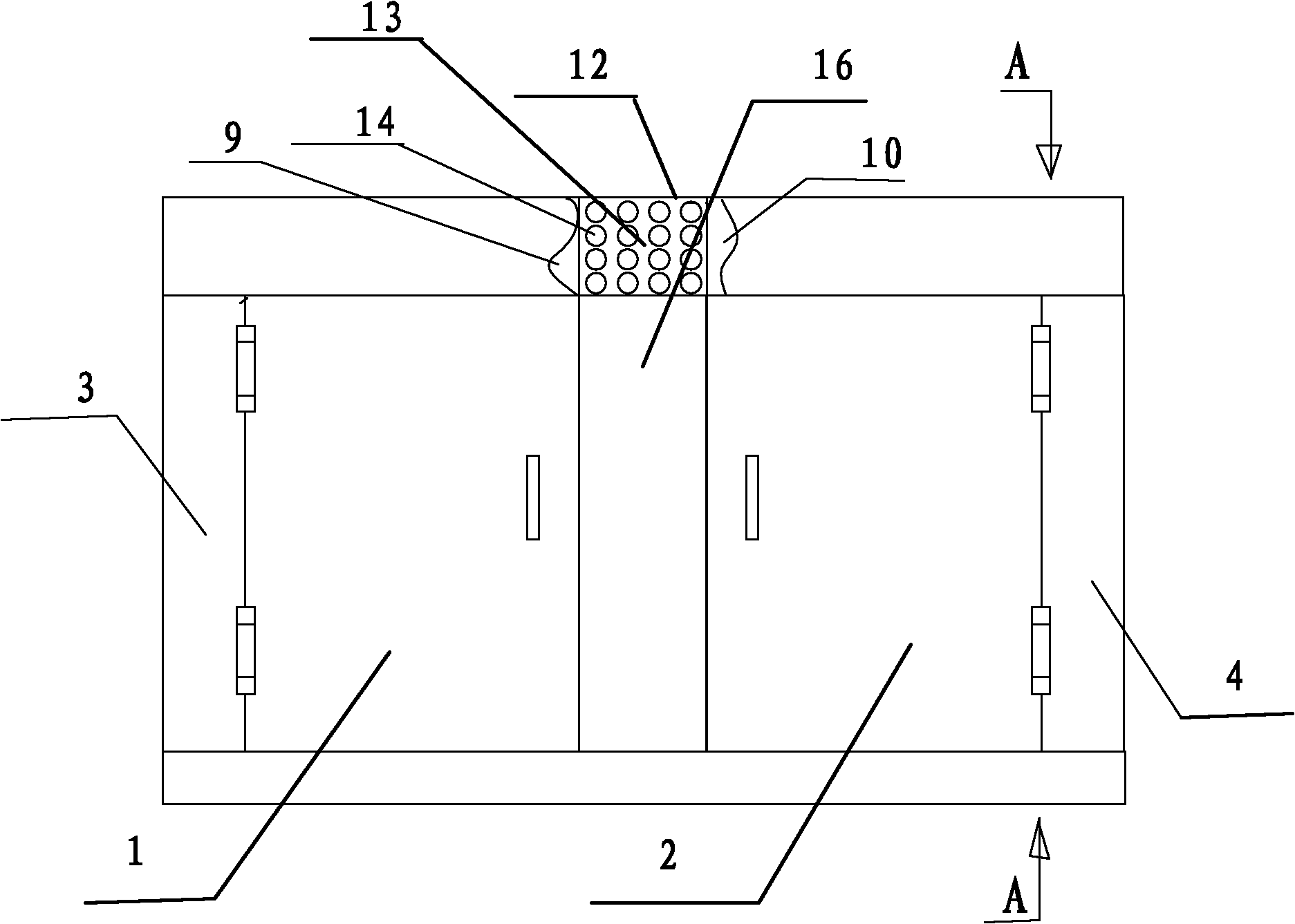
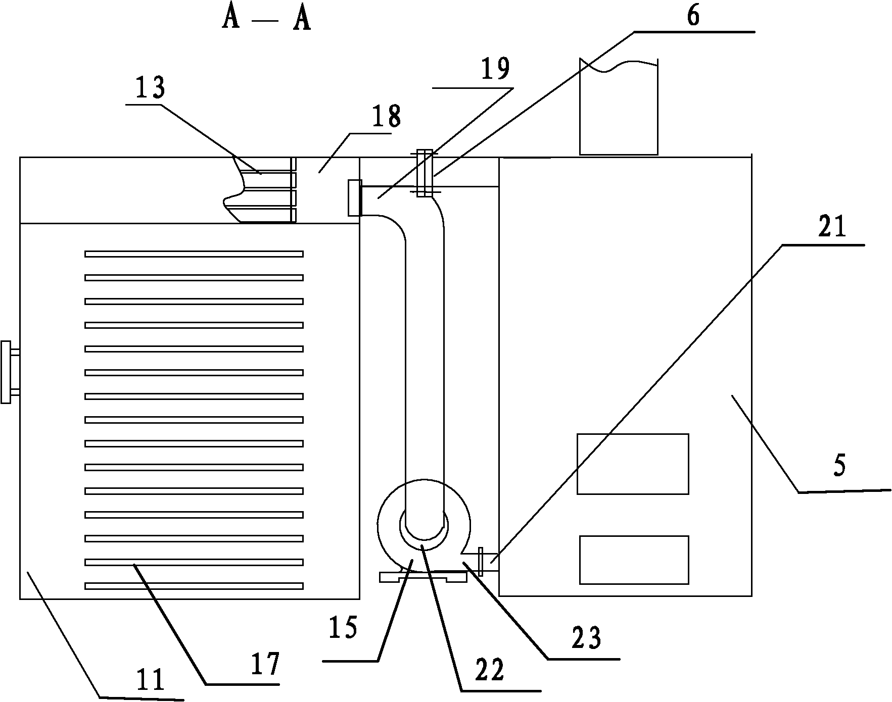
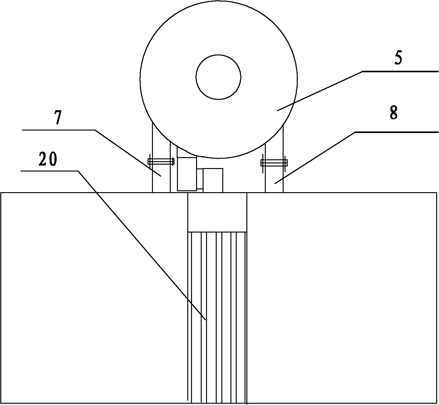
[0010] see figure 1 , 2 , 3, in the picture, 1. left drying box, 2. right drying box, 3. left equalizing hot air box, 4. right equalizing hot air box, 5. hot blast stove, 6. hot air outlet, 7. left hot air output pipe, 8 .Right hot air output pipe, 9.Left hot air duct, 10.Right hot air duct, 11.Separator, 12.Waste heat recovery box, 13.Tubular heat exchanger, 14.Fresh air inlet, 15.Centrifugal fan, 16 .Humidity exhaust box, 17. Balanced air inlet, 18. Air collection box, 19. Air duct, 20. Humidity exhaust port, 21. Air inlet of hot blast stove. 22. Air inlet of centrifugal fan.

[0011] The left drying box 1 and the right drying box 2 are respectively arranged on the left and right sides of the moisture removal box 16, and the left end of the left drying box 1 is provided with a balanced hot air box 3, and the right end of the right drying box 2 is provided with a balanced hot air box 4. The top of the dehumidification box 16 is provided with a waste heat recovery box 12. Th...


PUM


Abstract

The invention relates to drying boxes for a hot-blast air furnace. A humidity-discharging box is arranged in the middle of left and right drying boxes; balanced hot-blast air boxes are arranged at left and right ends of the left and right drying boxes; a waste heat recovery box is arranged on the top of the humidity-discharging box; a tube type heat exchanger is arranged in the waste heat recovery box; the bottom of the tube type heat exchanger is communicated with the humidity-discharging box; a fresh air suction inlet is formed at the front end of the tube type heat exchanger, and an air-collecting box is arranged at the rear end of the tube type heat exchanger; the end part of the air-collecting box is connected with the air inlet of a centrifugal fan; the air outlet of the centrifugal fan is connected with the air inlet of a hot-blast air furnace; and the top of the waste heat recovery box is opening and is used as a humidity-discharging opening. In the drying boxes, a mode of hot-blast air flowing is changed effectively, so that wind resistance is small; and the relatively-small fan can be selected, electricity is saved, the temperature in the drying boxes is uniform, the drying quality is improved, and energy is saved for a considerable part of heat energy is recovered in discharged damp and hot air.

Description

[0001] Field: [0002] The invention relates to a drying device, especially a hot blast oven drying box with uniform ventilation in the drying box, small temperature difference between the upper and lower sides and the ability to recover a considerable part of heat energy. Background technique: [0003] At present, the known drying equipment for agricultural and sideline products has a structure that drying boxes are arranged on the left and right sides of the hot blast stove. The hot blast stove is a square box with closed sides and an open top. The combustion furnace is placed below the square box. An axial flow fan is installed above the combustion furnace. An air inlet is provided under the partition adjacent to the left and right drying boxes. The air is forced to flow under the action of the fan. After being heated by the combustion furnace, the air enters the bottom of the left and right drying boxes from the above-mentioned air inlet, and is discharged through 15-20 la...

Claims


Application Information

Patent Timeline
Patent Type & Authority Applications(China)
IPC IPC(8): F26B9/06F26B21/00
CPCY02P70/10
Inventor 李超
Owner 如皋市精艺标牌厂
Why Eureka
Try Eureka