Refrigerant distributing device and heat exchanger with same

A technology of refrigerant distribution and refrigerant, which is applied in the direction of heat exchanger shell, refrigeration and liquefaction, refrigerator, etc., can solve the problems of large gap in momentum, dispersion of liquid refrigerant, poor mixing effect, etc., and achieve reduction Stratification, improved heat transfer effect, and high heat transfer efficiency

Inactive Publication Date: 2011-05-25
SANHUA HANGZHOU MICRO CHANNEL HEAT EXCHANGER
View PDF10 Cites 7 Cited by
  • Summary
  • Abstract
  • Description
  • Claims
  • Application Information

AI Technical Summary

Problems solved by technology

However, the gaseous refrigerant sprayed from the gas nozzle 34 and the liquid refrigerant sprayed from the liquid nozzle 36 are directly opposed, and the mixing effect is not good, because the density of the gaseous refrigerant is much smaller than that of the liquid refrigera

Method used


Image

  • Refrigerant distributing device and heat exchanger with same
  • Refrigerant distributing device and heat exchanger with same
  • Refrigerant distributing device and heat exchanger with same

Examples


Example Embodiment

[0033] The embodiments of the present invention will be described in detail below. Examples of the embodiments are shown in the accompanying drawings, wherein the same or similar reference numerals indicate the same or similar elements or elements with the same or similar functions. The embodiments described below with reference to the drawings are exemplary, and are only used to explain the present invention, but should not be understood as limiting the present invention.

[0034] In the description of the present invention, it should be understood that the terms "longitudinal", "lateral", "upper", "lower", "front", "rear", "left", "right", "vertical", The orientation or positional relationship indicated by "horizontal", "top", "bottom", "inner", "outer", etc. is based on the orientation or positional relationship shown in the drawings, and is only for the convenience of describing the present invention and simplifying the description, not It indicates or implies that the pointe...


PUM


Abstract

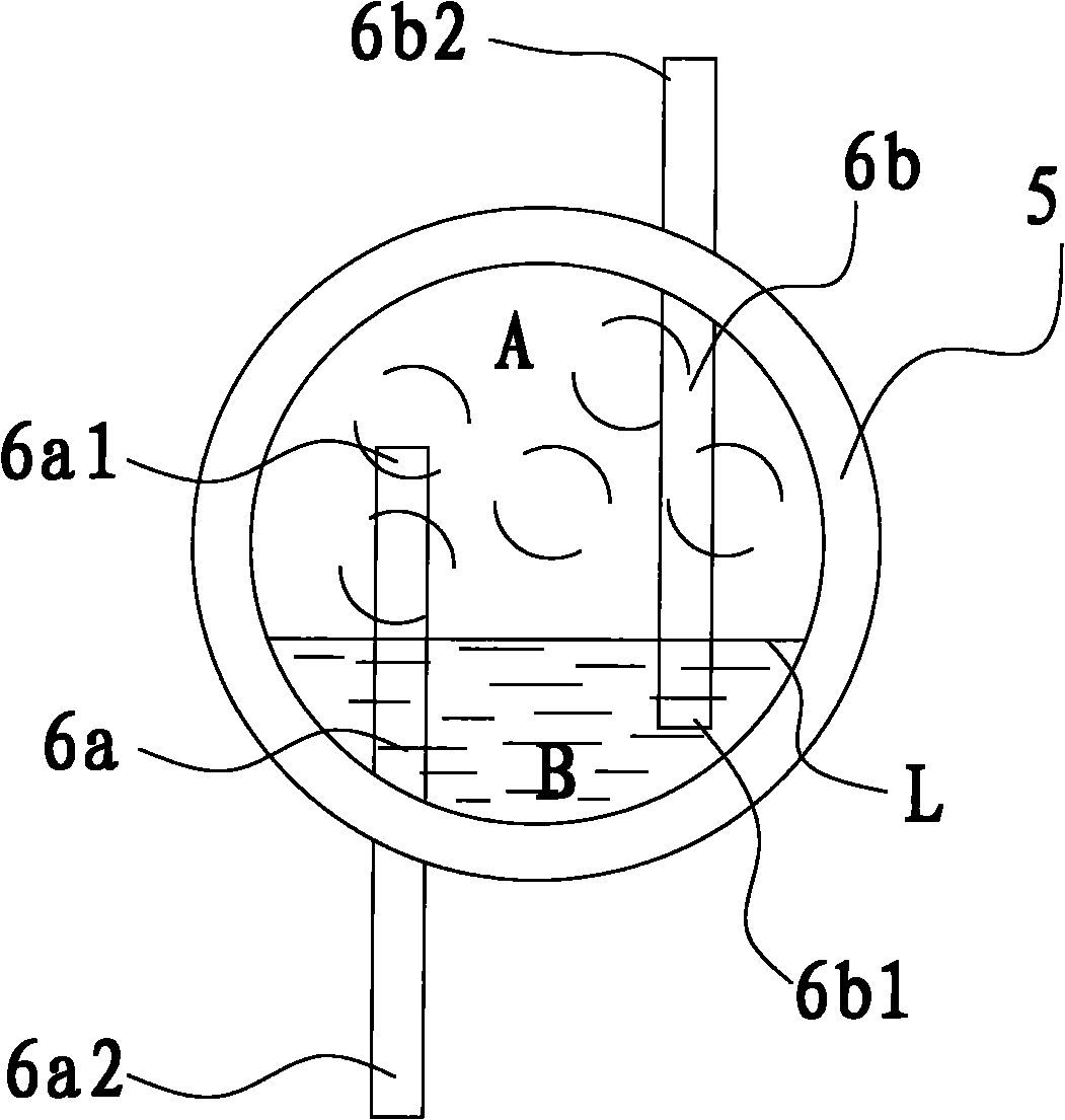
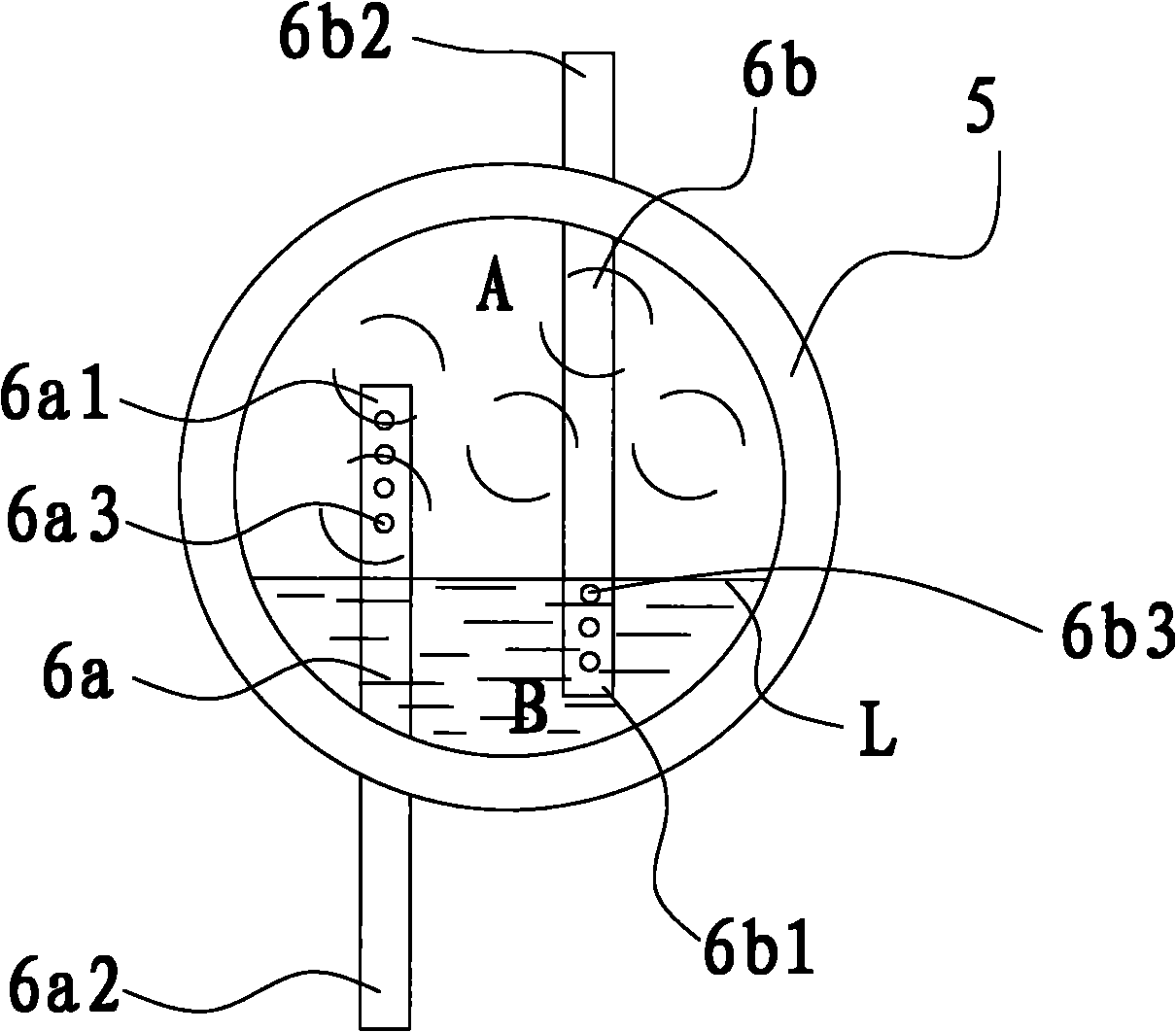
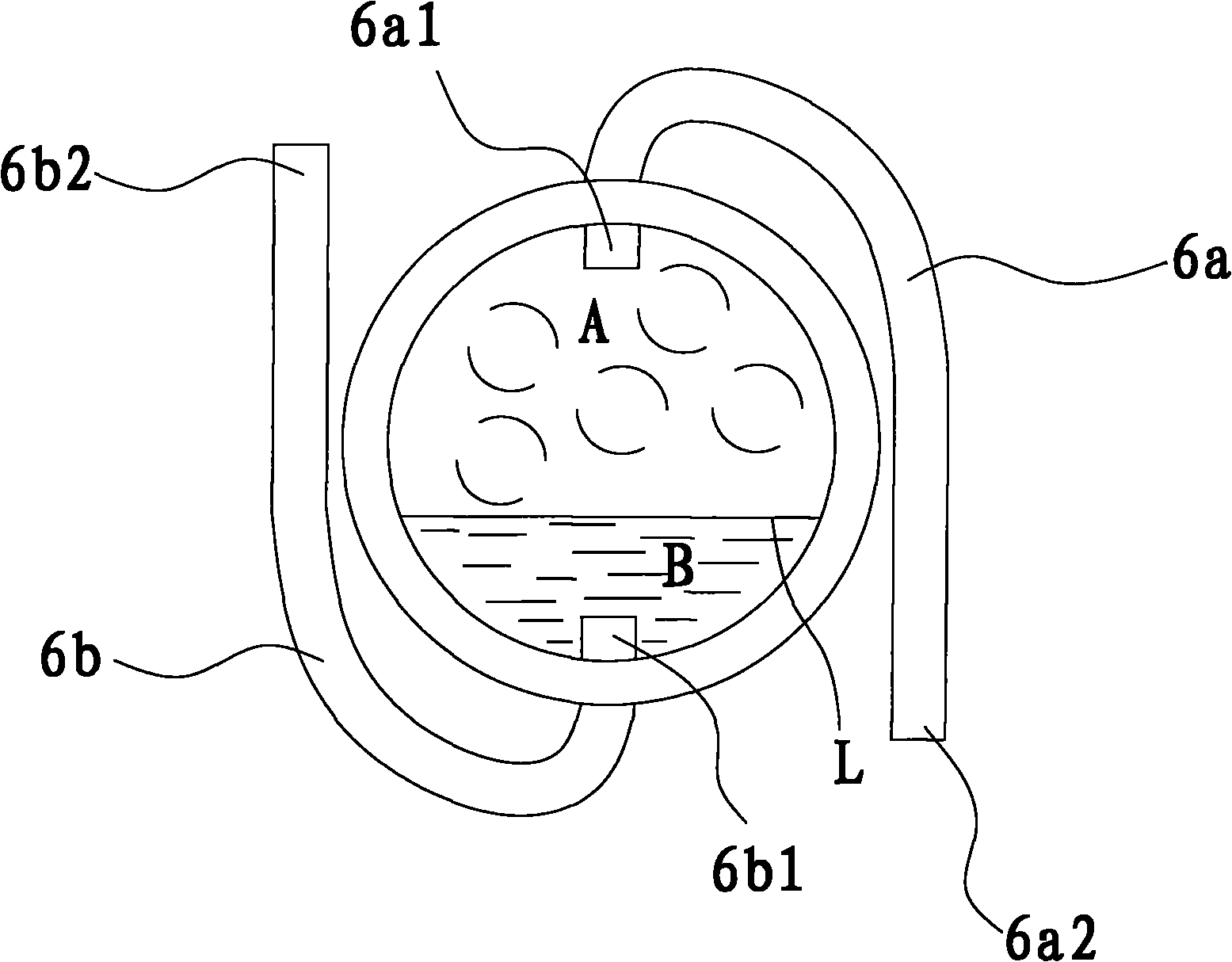
The invention provides a refrigerant distributing device and a heat exchanger with the same. The refrigerant distributing device comprises a conduit, a first distributing pipe and a second distributing pipe, wherein the inner cavity of the conduit is divided into an upper cavity and a lower cavity; the first distributing pipe is provided with a gas phase refrigerant inlet and a gas phase refrigerant outlet and limits a first end inserted into the conduit and a second end extending out of the conduit; the gas phase refrigerant inlet is arranged in the upper cavity; the gas phase refrigerant outlet is arranged outside the conduit, with the opening downward; the second distributing pipe is provided with a liquid phase refrigerant inlet and a liquid phase refrigerant outlet and limits a first end inserted into the conduit and a second end extending out of the conduit; the liquid phase refrigerant inlet is arranged in the lower cavity; and the liquid phase refrigerant outlet is arranged outside the conduit, with the opening upward. The refrigerant distributing device has the following advantage: the gas phase and liquid phase refrigerants are mixed uniformly, thus the heat exchange efficiency is high.

Description

technical field [0001] The invention relates to a refrigerant distribution device and a heat exchanger with the refrigerant distribution device. Background technique [0002] In traditional heat exchangers, in order to improve heat exchange performance, a refrigerant distribution device is usually provided in the inlet header of the heat exchanger. For example, Chinese patent application CN101031762A describes a refrigerant distribution device in which a small-diameter conduit is provided in the inlet channel, wherein the inlet end of the small-diameter conduit is inserted into the liquid-phase fluid below the refrigerant gas-liquid interface in the inlet channel Inside, the outlet port is located outside the inlet channel. [0003] When the gas-liquid two-phase fluid flows in the inlet channel, gas-liquid stratification will inevitably occur, with the gas phase on top and the liquid phase on top. For the above conventional refrigerant distribution equipment, the inlet end...

Claims


Application Information

Patent Timeline
IPC IPC(8): F28F9/02
CPCF25B39/028F28F9/0273
Inventor 刘华钊黄宁杰
Owner SANHUA HANGZHOU MICRO CHANNEL HEAT EXCHANGER
Why Eureka
Try Eureka