
Imaging device of handheld ultra-low-field MRI (magnetic resonance imaging) system

An imaging device and ultra-low field technology, applied in magnetic resonance measurement, magnetic performance measurement, scientific instruments, etc., can solve problems such as inability to compact layout, inability to realize hand-held MRI systems, inability to package magnetic flux detectors together, etc.

Active Publication Date: 2011-05-25
SHANTOU DONGFANG ULTRASONIC TECH
View PDF3 Cites 3 Cited by
  • Summary
  • Abstract
  • Description
  • Claims
  • Application Information

AI Technical Summary

Problems solved by technology

[0006] However, if the MRI machine is reduced to a hand-held range, the polarizing coil and the gradient coil will inevitably be on the same side of the object to be detected, and the magnetic field generated by it is very different from the standard magnetic field, and the magnetic fields generated by each coil will overlap. , very irregular, making it impossible to use the existing ultra-low field MRI magnetic resonance imaging algorithm to reconstruct images, which is a difficult place to break through
Due to the limitations of the algorithm, it is impossible to package the polarization coil, gradient coil and magnetic flux detector together, and the layout cannot be compact, and the hand-held MRI system cannot be realized

Method used


Image

  • Imaging device of handheld ultra-low-field MRI (magnetic resonance imaging) system
  • Imaging device of handheld ultra-low-field MRI (magnetic resonance imaging) system
  • Imaging device of handheld ultra-low-field MRI (magnetic resonance imaging) system

Examples


Embodiment approach 1

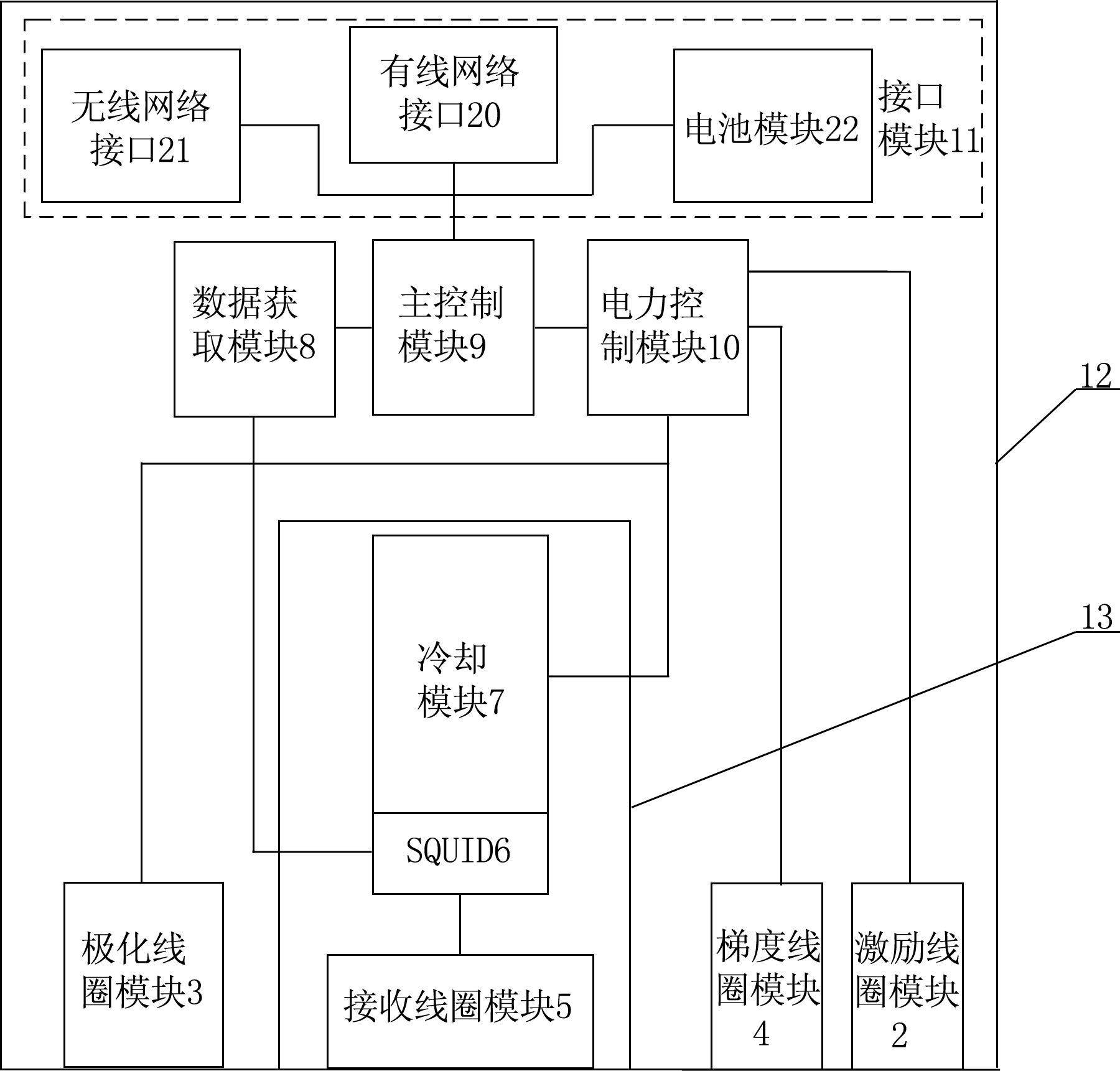
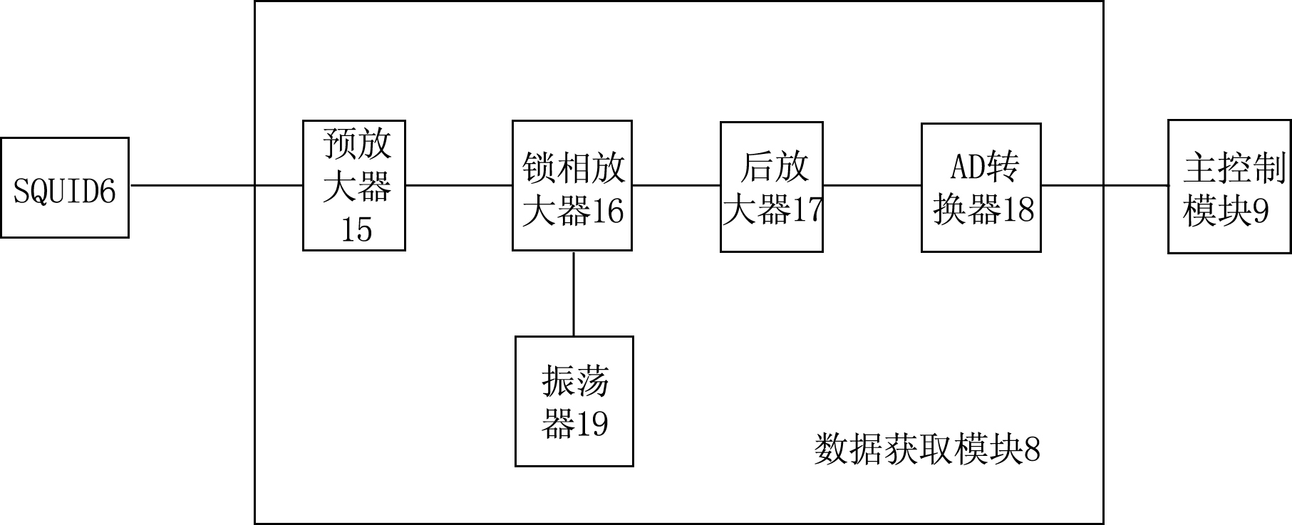
[0025] Such as figure 1 and Figure 4 As shown, this handheld ultra-low field MRI imaging device includes a hardware part and a software part, and the hardware part includes a smart handheld device 1, an excitation coil module 2, a polarization coil module 3, a gradient coil module 4, and a receiving coil module 5 , SQUID6, cooling module 7, data acquisition module 8, main control module 9, power control module 10, interface module 11 and probe housing 12; cooling module 7 is in contact with SQUID6; polarizing coil module 3, gradient coil module 4, receiving coil Both the module 5 and the SQUID6 are located inside the probe shell 12; the interface module 11 is connected to the smart handheld device 1 through a local area network; the software part is set on the smart handheld device 1, and the software part includes a magnetic field parameter transformation module and an image reconstruction module. The excitation coil module 2 and the cooling module 7 are arranged inside the...

Embodiment approach 2

[0036] In the case where other situations are the same as Embodiment 1, the difference is that at least three gradient coils are geometrically coded so that each voxel unit of the object to be measured is in a different frequency, phase, and excitation layer. In the software part In the magnetic field parameter transformation module, magnetic field parameter transformation is performed on all magnetic resonance signals acquired in a space volume, and the operation is repeated continuously.

[0037] In other embodiments, the excitation coil module may not be packaged inside the probe housing.


PUM


Abstract

The utility model relates to an imaging device of a handheld ultra-low-field MRI (magnetic resonance imaging) system, which comprises a hardware part and a software part. The hardware part comprises an intelligent handheld device, a polarizing coil module, a gradient coil module, a receiving coil module and a magnetic flux probe, the software part is arranged on the intelligent handheld device and comprises a probe shell; the polarizing coil module, the gradient coil module, the receiving coil module and the magnetic flux probe are all arranged in the probe shell; and the software part also comprises a magnetic field parameter transformation module and an image reconstruction module. The magnetic field parameter transformation module transforms irregular magnetic field parameters detected by the magnetic flux probe into magnetic field parameters suitable for the existing magnetic resonance imaging algorithm, and images can be reconstructed by adopting the existing magnetic resonance imaging algorithm. Therefore, the polarizing coil module, the gradient coil module, the receiving coil module and the magnetic flux probe are arranged on the same side of an object to be tested, and the MRI system can be handheld, can substitute the 0.1-1T permanent magnet MRI equipment, and is suitable for small and medium hospitals.

Description

technical field [0001] The invention relates to a magnetic resonance imaging device, in particular to a handheld ultra-low field MRI imaging device. Background technique [0002] Existing MRI (Magnetic Resonance Imaging, magnetic resonance imaging), its hardware equipment mainly includes computer, magnet (or polarizing coil), gradient coil, exciting coil, magnetic flux probe, receiving coil, data acquisition module, main control module, power Control module and interface module. Among them, the excitation coil is placed close to the measured object to generate excitation signals to different parts of the tested object; the magnet (or polarized coil) and the gradient coil are evenly arranged around the measured object to generate regular Magnetic field; the power control module is electrically connected to the data acquisition module, the main control module and the magnetic flux probe; the receiving coil is used to receive the magnetic resonance signal of the object under t...

Claims


Application Information

Patent Timeline
IPC IPC(8): G01R33/20
Inventor 林国臻李德来
Owner SHANTOU DONGFANG ULTRASONIC TECH
Learn More