
Vehicle reversing radar testing rack

A test bench, reversing radar technology, applied in radio wave measurement systems, instruments, etc., can solve the problems of prolonging the test and development time, detection range error, affecting the real vehicle test, etc., to shorten the test and development time, and facilitate the operation. , the effect of simple structure

Inactive Publication Date: 2011-05-25
CHERY AUTOMOBILE CO LTD
View PDF2 Cites 16 Cited by
  • Summary
  • Abstract
  • Description
  • Claims
  • Application Information

AI Technical Summary

Problems solved by technology

When using a computer to simulate the position of the probe, there is a large error between the detection range of the radar probe and the detection range of the real vehicle, which will affect the subsequent real vehicle test and prolong the test and development time. The reversing radar test bench for effectively verifying the position of the radar probe in the design stage

Method used


Image

  • Vehicle reversing radar testing rack
  • Vehicle reversing radar testing rack
  • Vehicle reversing radar testing rack

Examples


Embodiment 1

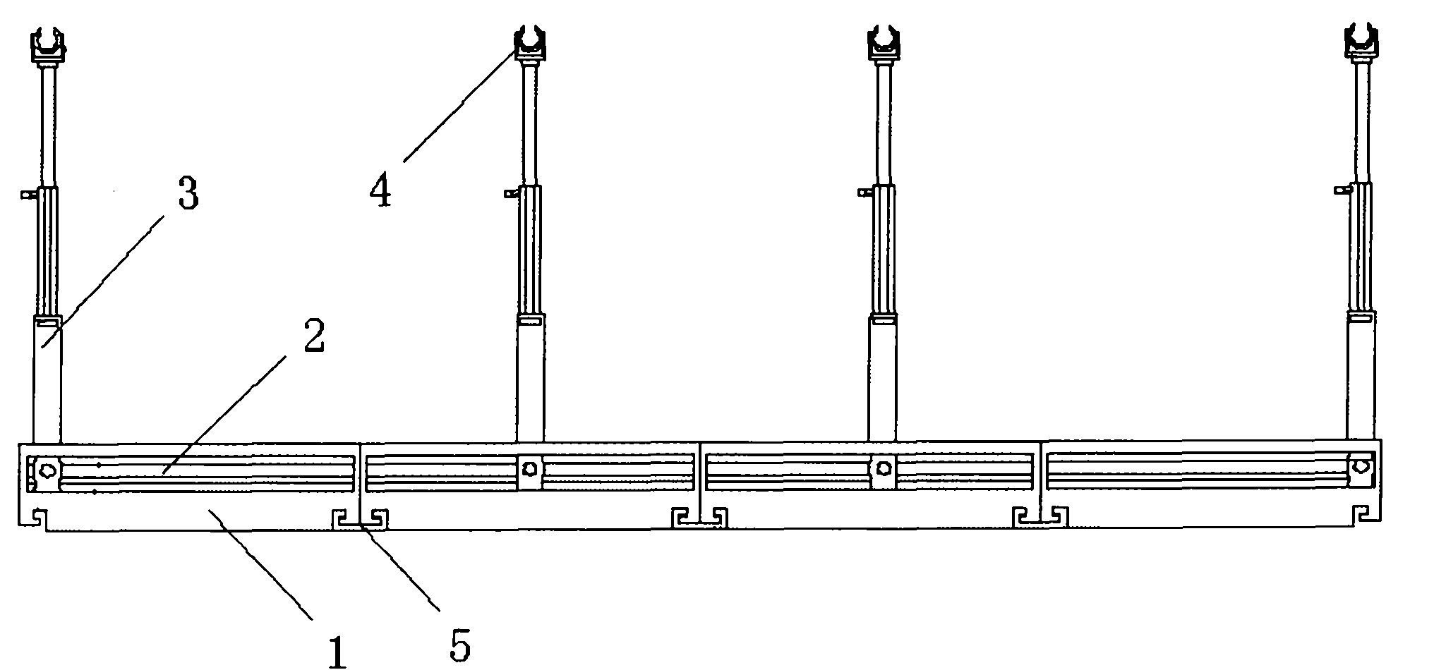
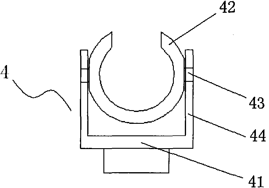
[0020] Such as figure 1 As shown, the reversing radar test stand of the present embodiment includes a base composed of four sub-bases 1, each sub-base 1 is provided with a horizontal chute 2, and a retractable vertical chute 2 is slidably installed on the chute 2. Straight probe bracket 3, the top of the probe bracket 3 is provided with a movable probe clip 4, the sub-base 1 is slidably installed on the guide rail 5, and the direction of the guide rail 5 is perpendicular to the direction of the chute 2.

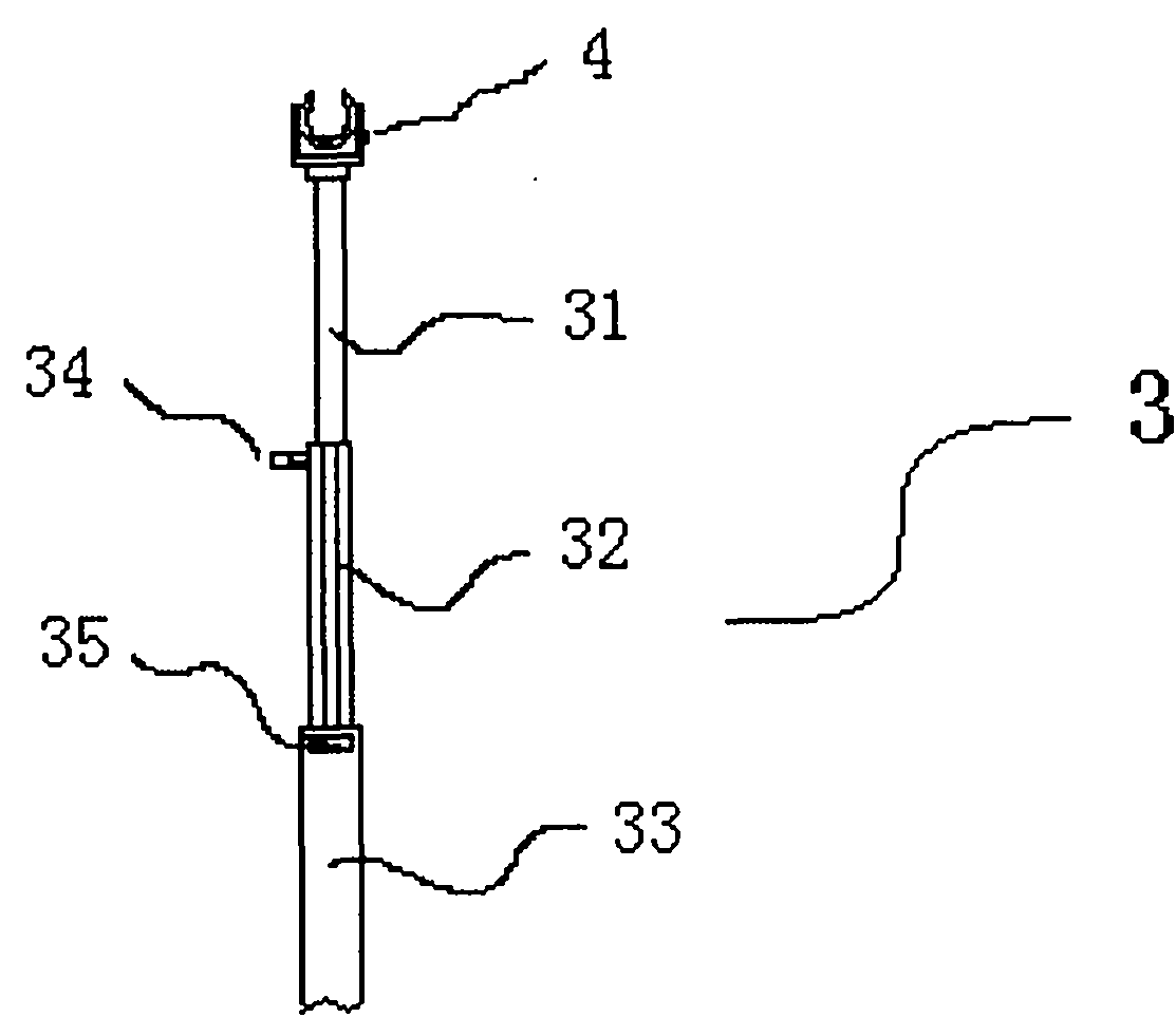
[0021] Such as figure 2 As shown, the probe bracket 3 is formed by socketing three hollow tubes 31, 32, 33 with different diameters, wherein the tube walls of the hollow tubes 32, 33 with larger diameters are respectively equipped with adjusting bolts 34, 35, and the adjusting bolts 34 extend The adjusting bolt 35 extends into the inside of the hollow tube 33 and is offset against the hollow tube 32 . By changing the socket depth of the hollow tubes 31, 32, 33, the length ...


PUM


Abstract

The invention provides a vehicle reversing radar testing rack which can simulate probe installing positions of a real car to ensure an effective verification of detection range and detection distance of radar probes during the stage of design before assembly, so that a vehicle reversing radar system can satisfy design requirements and meet business standards, and testing and development period can be shortened. The reversing radar compromises a base whereon a sliding groove is arranged, a plurality of telescopic vertical probe supports are installed on the sliding groove in a manner of sliding, and movable probe clips are installed on top of the probe supports. During the development, the radar probes can be installed on the probe clips, and the distance between each two probe supports can be adjusted by sliding. Then, by changing positions and angles of the probe clips, the installation positions and angles of the radar probes in a real car are simulated, and the detection range and the detection distance of the radar probes can be effectively verified.

Description

technical field [0001] The invention belongs to the technical field of auto parts testing, and in particular relates to a test bench for reversing radar of an automobile. Background technique [0002] With the development of the automobile industry, people have higher and higher requirements for car safety and driving comfort, and the application of reversing radar auxiliary systems is becoming more and more extensive. Many cars are equipped with several radars at the front and rear. probe. At present, the design process of the reversing radar system is as follows: use the computer to simulate the position of the probe layout, and then assemble the radar probe to the real vehicle for testing. When using a computer to simulate the position of the probe, there is a large error between the detection range of the radar probe and the detection range of the real vehicle, which will affect the subsequent real vehicle test and prolong the test and development time. The reversing r...

Claims


Application Information

Patent Timeline
Patent Type & Authority Applications(China)
IPC IPC(8): G01S7/40
Inventor 邢伟许佩玲奚叶飞刘宁吴静刘正国陈跃辉徐杰明邓军赵松岭
Owner CHERY AUTOMOBILE CO LTD
Learn More