
Portable electronic device, back cover structure thereof and manufacturing method of back cover structure

An electronic device, portable technology, applied in the direction of antenna support/installation device, etc., can solve the problems of limiting the size and shape of the antenna, occupying space, and the internal space of the mobile phone cannot be further effectively used, so as to increase the space Effect

Inactive Publication Date: 2011-05-25
INVENTEC CORP
View PDF0 Cites 3 Cited by
  • Summary
  • Abstract
  • Description
  • Claims
  • Application Information

AI Technical Summary

Problems solved by technology

However, the antenna installed on the motherboard not only takes up a lot of space, but also limits the size and shape of the antenna, so that the internal space of the mobile phone cannot be further effectively utilized.

Method used


Image

  • Portable electronic device, back cover structure thereof and manufacturing method of back cover structure
  • Portable electronic device, back cover structure thereof and manufacturing method of back cover structure
  • Portable electronic device, back cover structure thereof and manufacturing method of back cover structure

Examples


Embodiment Construction

[0024] According to the structure of the back cover of the portable electronic device according to one embodiment of the present invention, the thin antenna is disposed in the cover. When the cover is connected to the body, the electrical pins can contact the thin antenna exposed in the opening for signal transmission. Because the antenna is located in the cover, it does not occupy the space on the main board of the portable electronic device, which can improve the utilization rate of the space on the main board.

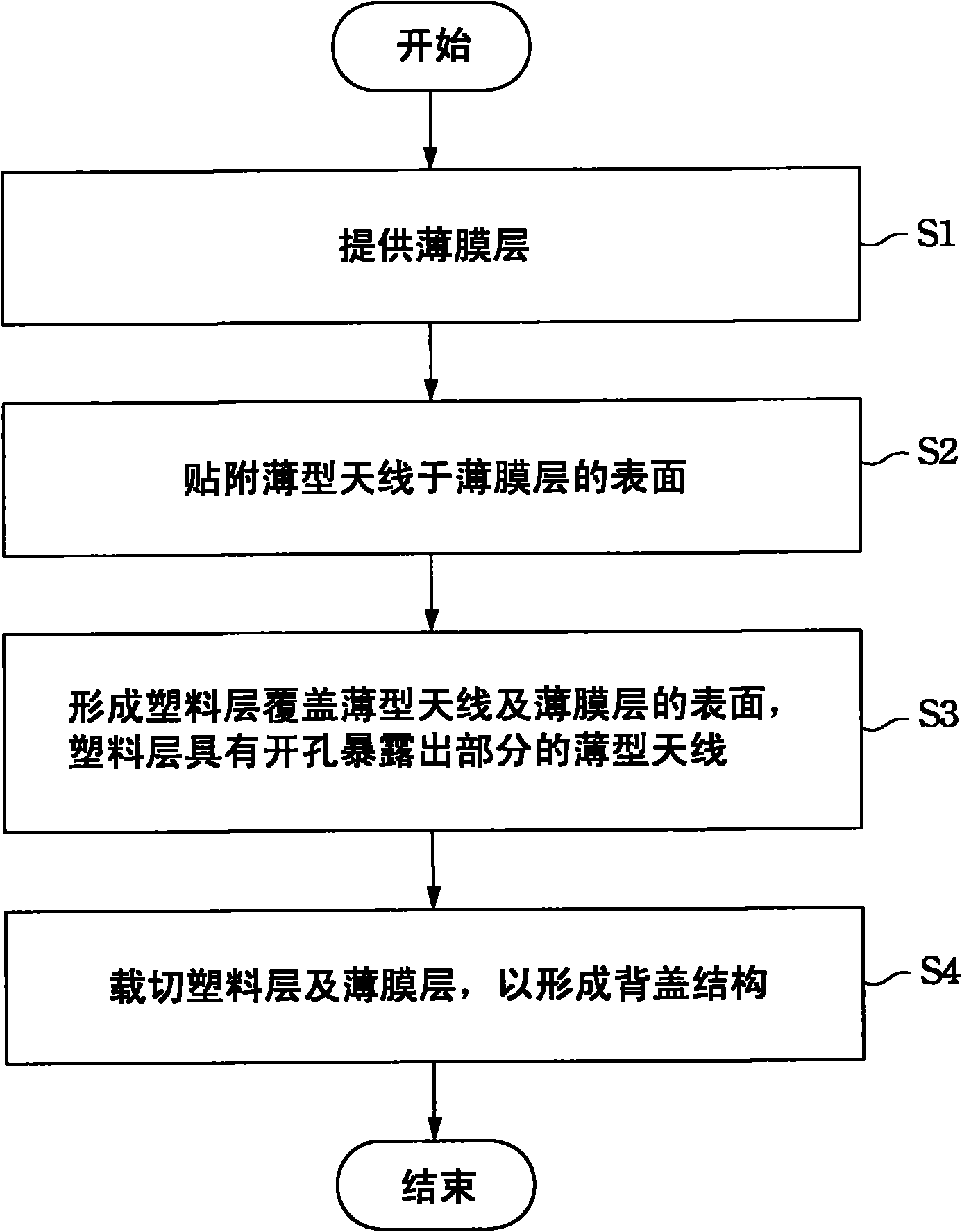
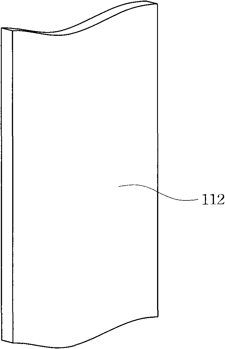
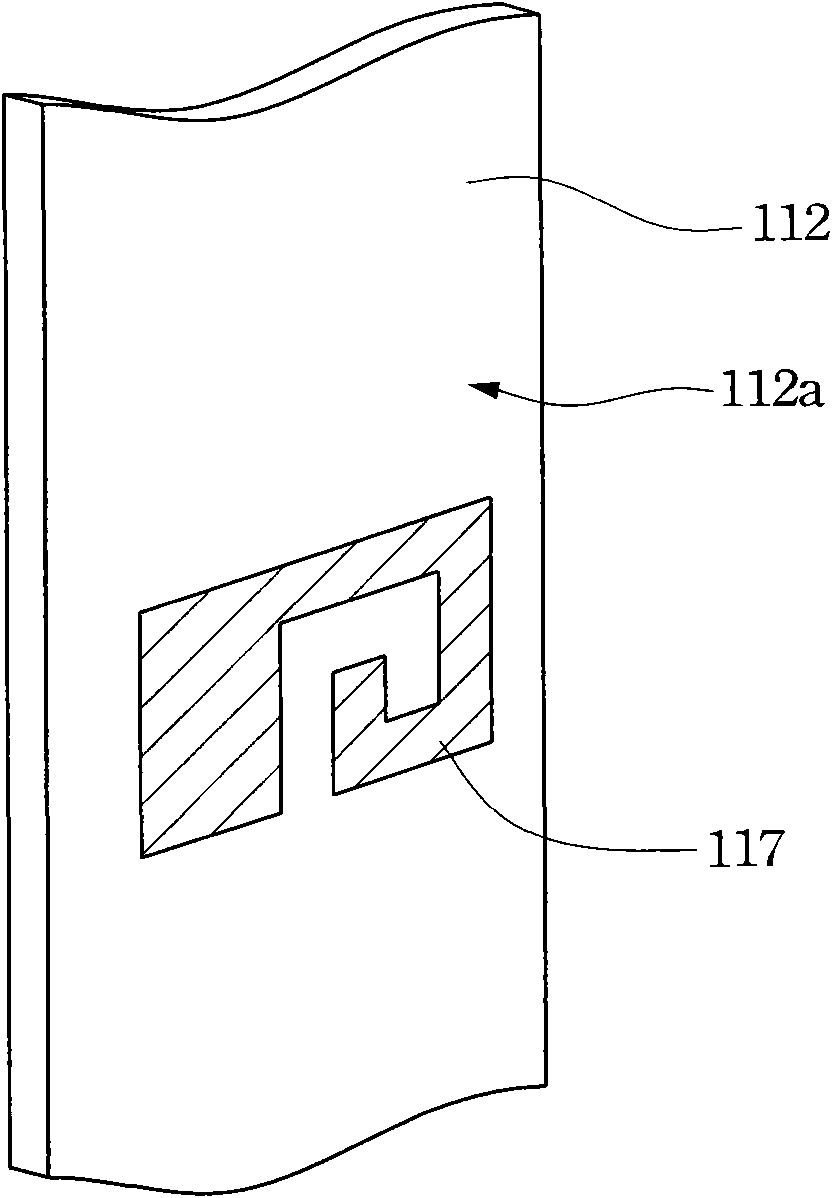
[0025] Firstly, the method for manufacturing the back cover structure according to an embodiment of the present invention will be described in detail. Please refer to figure 1 , which shows a flow chart of a manufacturing method of the back cover structure according to an embodiment of the present invention. In addition, please also refer to Figure 2A-2D , which respectively show figure 1 A schematic diagram of the steps. The manufacturing method of this embod...


PUM


Abstract

The invention discloses a portable electronic device, a back cover structure thereof and a manufacturing method of the back cover structure. The portable electronic device comprises a machine body and the back cover structure. The back cover structure comprises a cover body and a thin antenna, wherein the cover body is used for connecting the machine body; the thin antenna is arranged in the cover body; and an opening hole is formed on the cover body to expose a part of the thin antenna. When the cover body is connected to the machine body, an electric pin of the machine body contacts the thin antenna and is exposed at the opening hole; and the thin antenna is electrically connected to a radio frequency component of the machine body. The manufacturing method of the back cover structure comprises the following steps of: firstly, providing a thin film layer and sticking the thin antenna on the surface of the thin film layer; secondly, forming a plastic layer on the surfaces of the thin antenna and the thin film layer, wherein the opening hole is formed on the plastic layer and a part of the thin antenna is exposed from the opening hole; and finally, cutting the plastic layer and the thin film layer to form the back cover structure.

Description

technical field [0001] The present invention relates to a back cover structure and a manufacturing method thereof, and in particular to a back cover structure of a portable electronic device and a manufacturing method thereof. Background technique [0002] With the development of science and technology, all kinds of electronic devices have filled our daily life and become an indispensable tool for modern people. For example, the popularization of mobile phones has changed the communication mode of modern people. Users can now contact distant relatives and friends anytime and anywhere. The mobile phone has also developed from a single call function in the past to a multimedia device integrating various functions such as audio-visual playback, image capture, and data transmission. However, with the increasingly complex functions of mobile phones and the market's demand for miniaturization in size and weight, how to effectively utilize the limited space inside the mobile phone...

Claims


Application Information

Patent Timeline
IPC IPC(8): H01Q1/22H01Q1/24
Inventor 陈皇吉
Owner INVENTEC CORP
Learn More