Solution to working power supply and power of two-wire-system electronic switch

A technology of electronic switch and working power supply, which is applied in the direction of electric light source, lamp circuit layout, output power conversion device, etc., and can solve problems such as inappropriate voltage division method, low product power, and large heat generation of power semiconductor switching devices.

Inactive Publication Date: 2011-05-25
尹文庭
View PDF0 Cites 27 Cited by
  • Summary
  • Abstract
  • Description
  • Claims
  • Application Information

AI Technical Summary

Problems solved by technology

Due to the large power consumption of the existing two-wire electronic switch and the inappropriate voltage division method, the power semiconductor switching device generates a lot of heat, so the product power is made relatively small

Method used


Image

  • Solution to working power supply and power of two-wire-system electronic switch
  • Solution to working power supply and power of two-wire-system electronic switch
  • Solution to working power supply and power of two-wire-system electronic switch

Examples


Embodiment Construction

[0018] The present invention will be described in detail below in conjunction with the accompanying drawings.

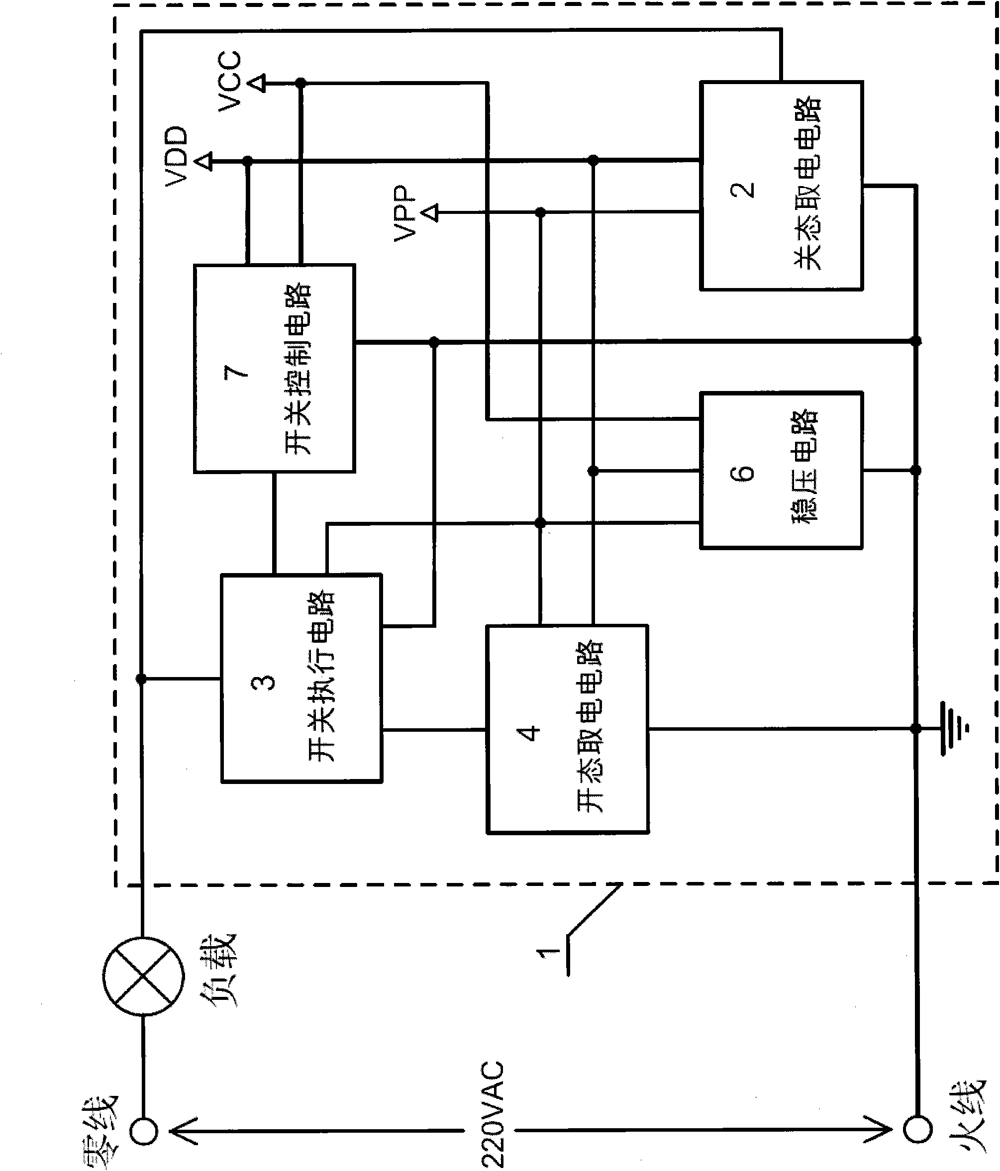
[0019] like figure 1 As shown, the two-wire electronic switch (1) is connected in series with the live wire and the neutral wire of the mains with the load.

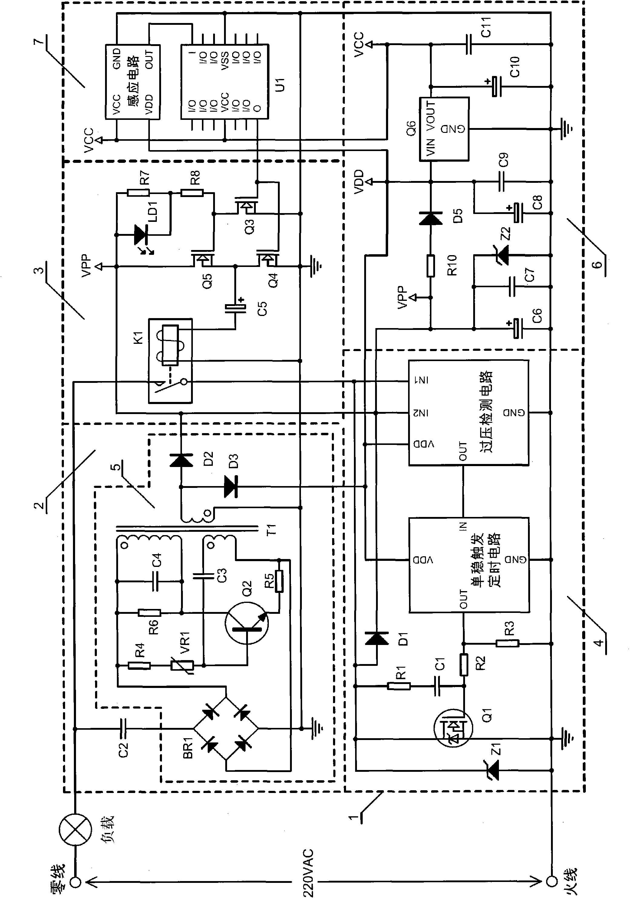
[0020] like figure 2 As shown, the two-wire electronic switch (1) consists of an off-state power-taking circuit (2), a switch execution circuit (3), an on-state power-taking circuit (4), a voltage stabilizing circuit (6), and a switch control circuit (7) composition. VPP, VDD, and VCC are the working DC power supplies of the electronic switches, all of which are positive voltages, and share the DC power ground. VPP provides working power for the switch execution circuit (3). VDD provides working power for the switch control circuit (7) and the open-state power-taking circuit (4). VCC provides working power for the switch control circuit (7), and its voltage value is consistent with the working voltage of th...


PUM


Abstract

The invention relates to a solution to a working power supply and the power of a two-wire-system electronic switch, relating to the field of illuminating electronic switches. The two-wire-system electronic switch comprises an off-state electrification circuit, a switch executive circuit, an on-state electrification circuit, and the like, wherein when loads are closed, the off-state electrification circuit supplies working electric energy for the electronic switch and also eliminates the sparkling phenomenon of a load lamp; the switch executive circuit is used for executing the starting or the closing of the loads, not only has low power consumption, but also provides the switch state indication; and when the loads are started, the on-state electrification circuit provides a heavy current path for the loads and also supplies the working electric energy for the electronic switch. The invention not only solves the problem on the working power supply of the two-wire-system electronic switch, but also enhances the loading capacity of the two-wire-system electronic switch.

Description

technical field [0001] The invention relates to the field of lighting electronic switches, and can be applied to two-wire wireless radio frequency remote control switches, infrared remote control switches, human body infrared induction switches, sound and light control switches, touch switches, timing switches and the like. Background technique [0002] When the load is turned off, the two-wire electronic switch relies on the leakage current flowing through the load to obtain operating power. If the leakage current is too small, it will cause the two-wire electronic switch to fail to work normally due to insufficient operating current or voltage. Conversely, if the leakage current is large, when controlling energy-saving lamps and fluorescent lamps, these lamps will flash frequently after the lights are turned off. Because the existing two-wire electronic switch cannot solve the leakage current problem, it either works unstable or has poor performance, or the load lamp freq...

Claims


Application Information

Patent Timeline
Patent Type & Authority Applications(China)
IPC IPC(8): H05B37/02H02M3/335
Inventor 尹文庭
Owner 尹文庭
Why Eureka
Try Eureka