
Pipe connector device

A connector and tubular technology, used in drill pipes, casings, couplings, etc., can solve the problems of excessive tooth wear and high contact pressure, reduce wear, simplify machining and inspection requirements, and reduce costs.

Inactive Publication Date: 2011-05-25
石油国家工业(英国)有限公司
View PDF7 Cites 1 Cited by
  • Summary
  • Abstract
  • Description
  • Claims
  • Application Information

AI Technical Summary

Problems solved by technology

[0007] However, this system has disadvantages because the tooth tips are no longer aligned on a single cone, and the uneven top profile creates points of high contact pressure during assembly, which can lead to excessive localized wear of the teeth

Method used


Image

  • Pipe connector device
  • Pipe connector device
  • Pipe connector device

Examples


Embodiment Construction

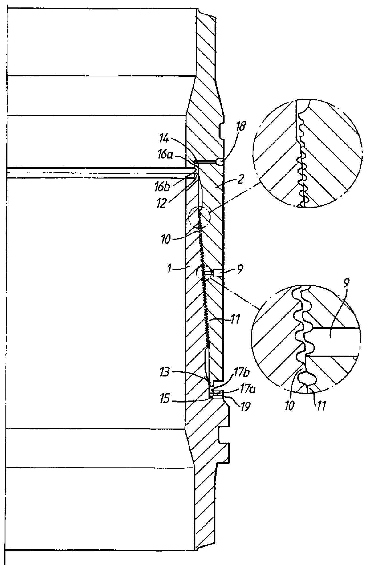
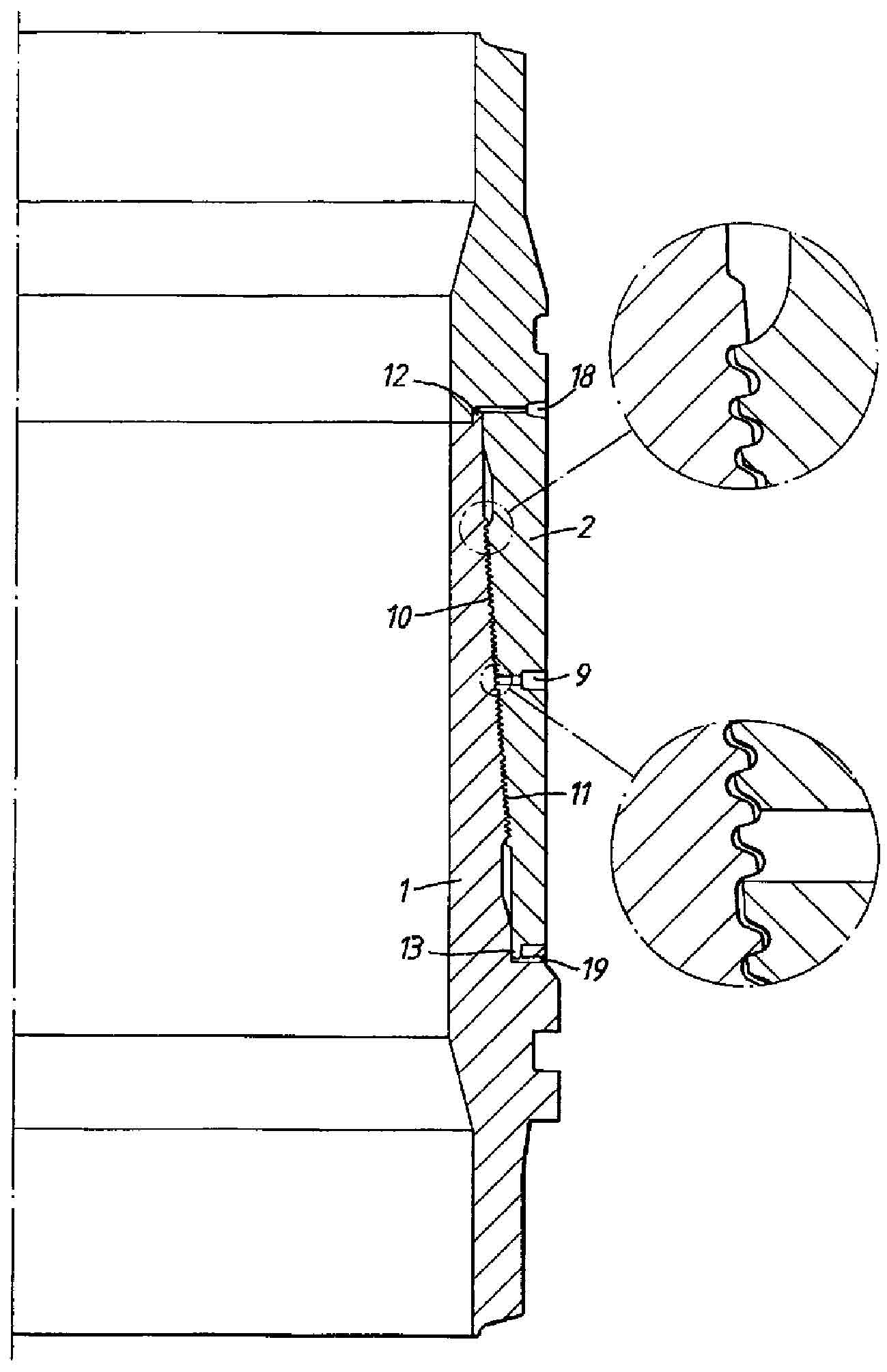
[0022] see first figure 1 and 2 , figure 1 and 2 A prior art pipe connector is shown comprising a tubular pin member 1 and a tubular box member 2 connected to Or it is connected to the ends of the two pipes, for example by welding. The pin member 1 and the box member 2 are designed to nest together, while both the outer surface 3 of the pin member 1 and the inner surface 4 of the box member 2 are generally frusto-conical and equipped with complementary protrusions. There are protrusions 5 and grooves 6 spaced axially along the length of the surface midway between the ends of the surface. The protrusions and grooves are relatively dimensioned so that when the pin and box members are fully engaged together, a corresponding one of the protrusions interengages in the groove to axially lock the two members together. The pin member 1 is described herein as having protrusions 5 and the box member 2 as having grooves 6, but it should be understood that these descriptions could be...


PUM


Abstract

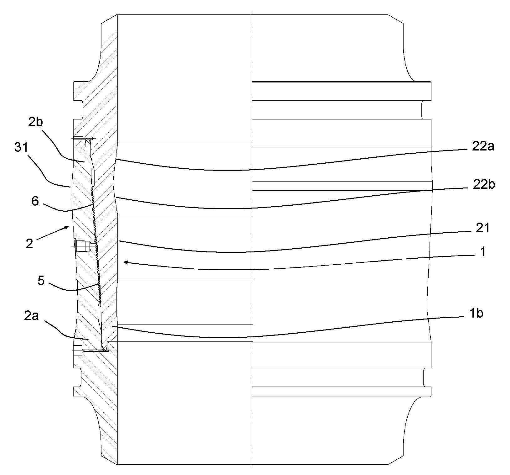
A pipe connector comprises a tubular pin member (1) having a frustoconical outer surface (3) and a tubular box member (2) having a frustoconical inner surface (4) corresponding to the outer surface (3) of the pin member (1) and which overlies the frustoconical surface (3) of the pin member (1) when the members (1, 2) are fully engaged. The members (1, 2) are provided with inter-engageable annular projections (5) and grooves (6) on the said peripheral surfaces( 3, 4) for axially locking the members together when they are fully engaged together. The projections (5) and grooves (6) are spaced apart along the surfaces (3, 4). The inner tubular surface (21) of the pin member (1) and an outer tubular surface (28) of the box member (2) each include at least one of a recess (22, 23, 32, 33) and / or a protrusion / radially enlarged section (34, 35) which reduces and / or increases the thickness of the tubular wall along the length of the associated member (1, 2) so as to balance the displacement of the members (1, 2) at different points along the length thereof under injection pressure.

Description

technical field [0001] The present invention relates to improvements in pipe connectors, especially, but not exclusively, for use in the petroleum industry for connecting metal pipe sections of a series of pipes. Background technique [0002] So-called Merlin-style pipe connectors are well known in the art for joining pipes together and are disclosed in GB 1573945, GB 2033518, GB 2099529, GB 2113335 and GB 2138089. The connection is formed by a tubular pin member having a frusto-conical outer peripheral surface and a tubular female connector member generally having a frusto-conical inner peripheral surface which is in contact with the pin The frusto-conical outer peripheral surface of the component corresponds. In use, two components, each related to a pipe segment, are sleeved together and locked axially together by cooperating with the annular protrusions and grooves on the above-mentioned peripheral surface, and the protrusions and grooves are spaced along the two surfac...

Claims


Application Information

Patent Timeline
Patent Type & Authority Applications(China)
IPC IPC(8): E21B17/046
CPCE21B17/046F16L37/62
Inventor D·J·E·摩根D·M·辛克莱尔
Owner 石油国家工业(英国)有限公司
Learn More