Positioning device for tool bit holder of diamond tool bit welding rack

A diamond cutter head and welding frame technology, applied in the field of machinery, can solve the problems of low heating and welding efficiency, reducing the welding quality of the cutter head, uneven heating of the cutter head, etc. Effect

Inactive Publication Date: 2014-12-17
项大清
View PDF8 Cites 0 Cited by
  • Summary
  • Abstract
  • Description
  • Claims
  • Application Information

AI Technical Summary

Problems solved by technology

[0002] The positioning device on the existing diamond cutter head welding frame cutter head clip generally includes a front clamping seat and a rear clamping seat facing to the setting and having a raised positioning block at its lower end, and a fixed clamping seat is arranged between the front and rear clamping seats. The positioning structure connected to the lifting mechanism of the cutter head and has a positioning column. When welding the cutter head, the positioning column is pressed against the upper surface of the cutter head, and the lower surface of the cutter head is against the saw blade. Since the positioning column is The saw blade is positioned at a single point, and the cutter head will rotate back and forth around the pressure point of the positioning column on the cutter head during welding. In order to overcome this problem, generally the positioning blocks on the front and rear clamping seats are clamped on the knife The cutter head is fixed on the two sides of the head and does not rotate, but there are some problems, mainly: the first is that part of the heat heated by the cutter head will be lost through the two positioning blocks, resulting in low heating and welding efficiency; Uniformity reduces the welding quality of the cutter head; the third is that the two positioning blocks are directly heated by high temperature, thereby reducing the service life

Method used


Image

  • Positioning device for tool bit holder of diamond tool bit welding rack
  • Positioning device for tool bit holder of diamond tool bit welding rack
  • Positioning device for tool bit holder of diamond tool bit welding rack

Examples


Embodiment Construction

[0022] The following are specific embodiments of the present invention and in conjunction with the accompanying drawings, the technical solutions of the present invention are further described, but the present invention is not limited to these embodiments.

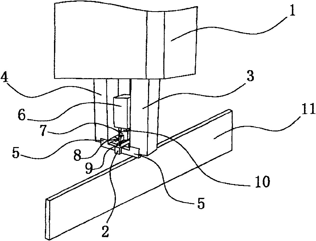
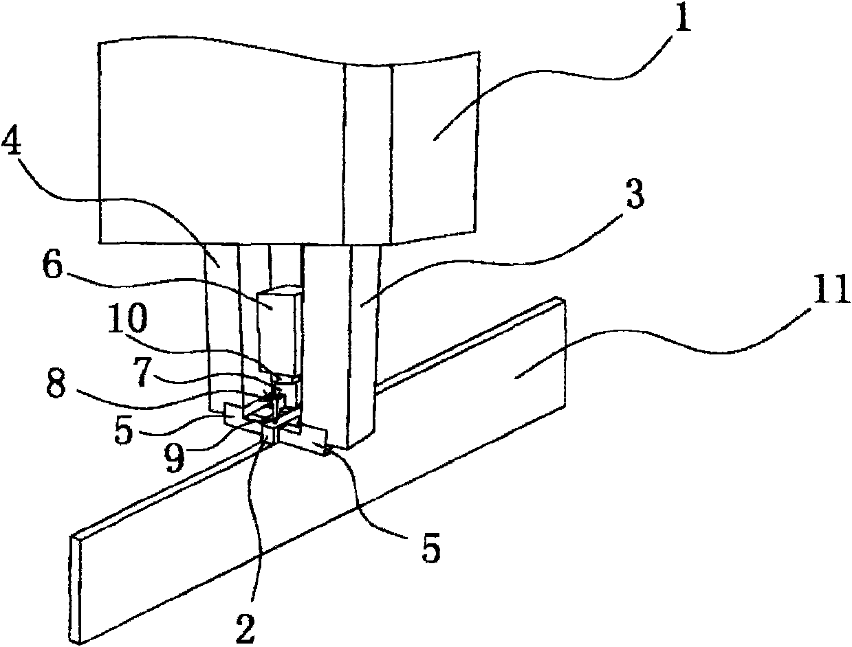
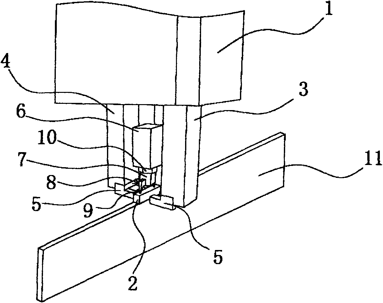
[0023] Such as figure 1 and 4 As shown, the positioning device on the cutter head holder of the diamond cutter head welding frame is set on the lifting mechanism 1 of the diamond welding machine cutter head holder, and is used for positioning the cutter head 2, including the facing setting and the lower end having a protrusion The front clamping seat 3 and the rear clamping seat 4 of the positioning block 5, the positioning block 5 is made of ceramics, the upper ends of the front clamping seat 3 and the rear clamping seat 4 are connected on the lifting mechanism 1 and the two positioning blocks 5 can clamp the cutter head 2 both sides. Between the front clamping seat 3 and the rear clamping seat 4, an extruding seat 6 fi...


PUM


Abstract

The invention provides a positioning device for a tool bit holder of a diamond tool bit welding rack, which belongs to the technical field of machinery and solves the problems of low tool bit welding efficiency and low quality of the conventional positioning device for the tool bit holder of the diamond tool bit welding rack. The positioning device for the tool bit holder of the diamond tool bit welding rack is arranged on a lifting mechanism of the tool bit holder of the diamond tool bit welding rack and used for positioning a tool bit, and comprises a front holding seat and a rear holding seat, wherein the front and rear holding seats are arranged opposite; the upper ends of the front and rear holding seats are provided with a protruded positioning block respectively; the upper ends of the front and rear holding seats are connected to the lifting mechanism; the two positioning blocks of the front and rear holding seats can clamp the two lateral surfaces of the tool bit; an extrusion seat fixedly connected to the lifting mechanism is arranged between the front and rear holding seats; a positioning structure with two sharp corners is arranged at the bottom end of the extrusion seat; and the two sharp corners can position the upper surface of the tool bit. The positioning device for the tool bit holder of the diamond tool bit welding rack has the advantages of high welding efficiency, high quality and long service life.

Description

technical field [0001] The invention belongs to the technical field of machinery, and relates to a positioning device, in particular to a positioning device on a cutter head holder of a diamond cutter head welding frame. Background technique [0002] The positioning device on the existing diamond cutter head welding frame cutter head clip generally includes a front clamping seat and a rear clamping seat facing to the setting and having a raised positioning block at its lower end, and a fixed clamping seat is arranged between the front and rear clamping seats. The positioning structure connected to the lifting mechanism of the cutter head and has a positioning column. When welding the cutter head, the positioning column is pressed against the upper surface of the cutter head, and the lower surface of the cutter head is against the saw blade. Since the positioning column is The saw blade is positioned at a single point, and the cutter head will rotate back and forth around the...

Claims


Application Information

Patent Timeline
Patent Type & Authority Patents(China)
IPC IPC(8): B23K37/04
Inventor 项大清
Owner 项大清
Why Eureka
Try Eureka