
Method for preventing and controlling heat hazard of mine

A technology of mine and evaporative heat exchanger, which is applied in mine/tunnel ventilation, mining equipment, earthwork drilling and mining, etc. It can solve the problems of increasing the workload of cooling and cooling, failing to achieve obvious cooling, repeated cooling and cooling, etc., to achieve Eliminate mine heat damage, easy equipment installation, high energy efficiency ratio of the system

Active Publication Date: 2011-06-01
姜玉贵
View PDF10 Cites 15 Cited by
  • Summary
  • Abstract
  • Description
  • Claims
  • Application Information

AI Technical Summary

Problems solved by technology

In order to cool down the excavation working face, according to the existing technology, pipelines are generally used to transport refrigerant, that is, local sealing and local cooling are adopted. The hot air after heat exchange is left in the unisolated roadway. The separate cooling and cooling of the mining face and the driving face increases the workload of cooling and cooling. On the other hand, it is easy to cause repeated cooling and cooling, resulting in a large amount of waste; and on the whole, the refrigeration equipment of the prior art They are all underground, and while controlling local high temperatures, a lot of heat is generated. Therefore, on the whole, local cooling and regional cooling cannot significantly reduce the temperature of the mine as a whole.

Method used


Image

  • Method for preventing and controlling heat hazard of mine
  • Method for preventing and controlling heat hazard of mine

Examples


Embodiment Construction

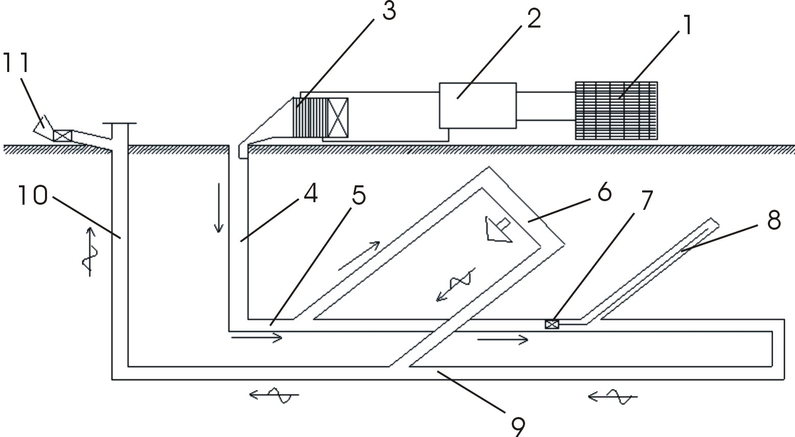
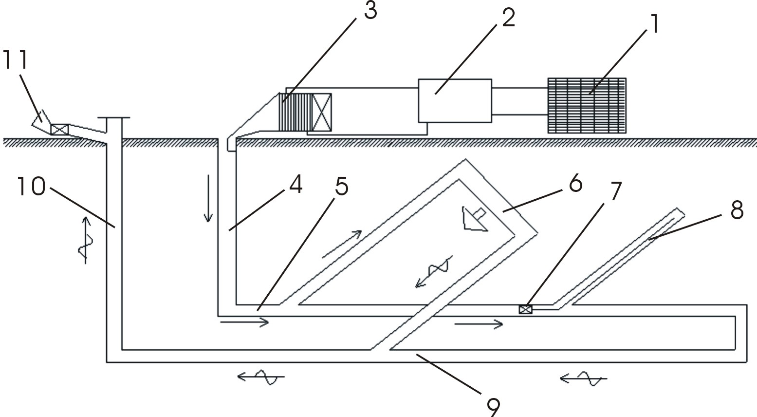
[0007] Now refer to the attached figure 1 , described in conjunction with the examples as follows: A method for preventing and controlling mine heat damage according to the present invention is to directly use a high-efficiency refrigeration unit to cool a part of the air entering the mine, and then mix it with other air entering the mine to form low-temperature air. , Through the existing mine ventilation system, it is sent to the underground working place to prevent and eliminate the hazards of underground high temperature and high humidity, and to improve the underground operating environment. The device adopted in the present invention includes a cooling tower 1, a refrigeration unit 2, an evaporative heat exchanger 3, an air inlet shaft 4, an air inlet roadway 5, a coal mining face 6, a local fan 7, an excavation face 8, a mine return Air lane 9, air return shaft 10 and mine main ventilator 11 form. Set up the refrigeration unit 2 on the ground, the refrigeration unit 2 ...


PUM


Abstract

The invention relates to a method for preventing and controlling heat hazards of a mine, comprising the following steps of: cooling a part of air entering the mine by directly utilizing a high-efficiency refrigerating unit; then mixing the part of air with other air entering the mine to form low-temperature air; and delivering the low-temperature air to an underground working place through the traditional mine ventilation system so as to achieve the purposes of preventing and eliminating underground high-temperature high-humidity hazards and improving underground operating environments. An adopted device comprises a cooling tower, the refrigerating unit, an evaporation heat exchanger, an intake shaft, an intake airway, a coal face, a local fan, a driving face, a mine return airway, a return air shaft and a mine main fan, wherein the refrigerating unit is arranged on the ground and connected with the cooling tower and the evaporation heat exchanger; an exhaust pipe of the evaporation heat exchanger is connected with the intake shaft; the lower side of the intake shaft is connected with the intake airway and connected with the coal face from the intake airway and returns to the mine return airway from the coal face; the mine return airway is connected with the return air shaft; and the foreshaft of the return air shaft is provided with a mine main fan. The invention has the advantages of easy equipment installation, maintenance and management and energy saving.

Description

technical field [0001] The invention relates to a method for processing hot air in coal mines, in particular to a method for preventing and controlling heat damage in mines. Background technique [0002] The depth of the fully mechanized mining face and the tunneling face of the coal mine generally exceeds 800 meters, especially the temperature of the gushing water at the tunneling face generally exceeds 45°C, which exceeds the stipulation in the "Coal Mine Safety Regulations" that construction can only be carried out at a temperature below 30°C. In order to cool down the excavation working face, according to the existing technology, pipelines are generally used to transport refrigerant, that is, local sealing and local cooling are adopted. The hot air after heat exchange is left in the unisolated roadway. The separate cooling and cooling of the mining face and the driving face increases the workload of cooling and cooling. On the other hand, it is easy to cause repeated coo...

Claims


Application Information

Patent Timeline
IPC IPC(8): E21F3/00
Inventor 杨子祥徐道之彭兴海姜超王洪轩闫亚运姜玉贵徐玉学王伟刘文江朱红卫王国栋冯鹏飞凌信东韩德成
Owner 姜玉贵
Learn More