Method and device suitable for laminating film for ultrathin wafer

A film sticking device and wafer technology, applied in the direction of electrical components, semiconductor/solid-state device manufacturing, circuits, etc., can solve the problems of easy damage, and achieve the effects of avoiding cracks, improving capabilities, and improving safety

Active Publication Date: 2011-06-01
上海技美科技股份有限公司
View PDF9 Cites 9 Cited by
  • Summary
  • Abstract
  • Description
  • Claims
  • Application Information

AI Technical Summary

Problems solved by technology

The disadvantage of this method is that the wafer needs to have a certain rigidity, therefore, its thickness is at least 200um
Wafers with a thickness of less than 200um are easily damaged by this method.

Method used


Image

  • Method and device suitable for laminating film for ultrathin wafer
  • Method and device suitable for laminating film for ultrathin wafer
  • Method and device suitable for laminating film for ultrathin wafer

Examples


Embodiment 2

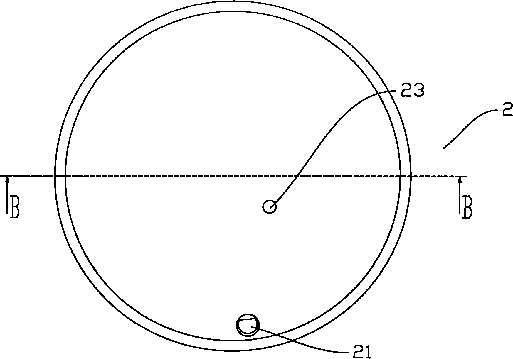
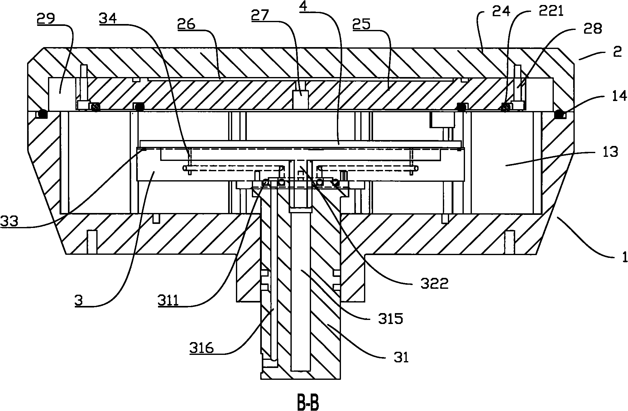
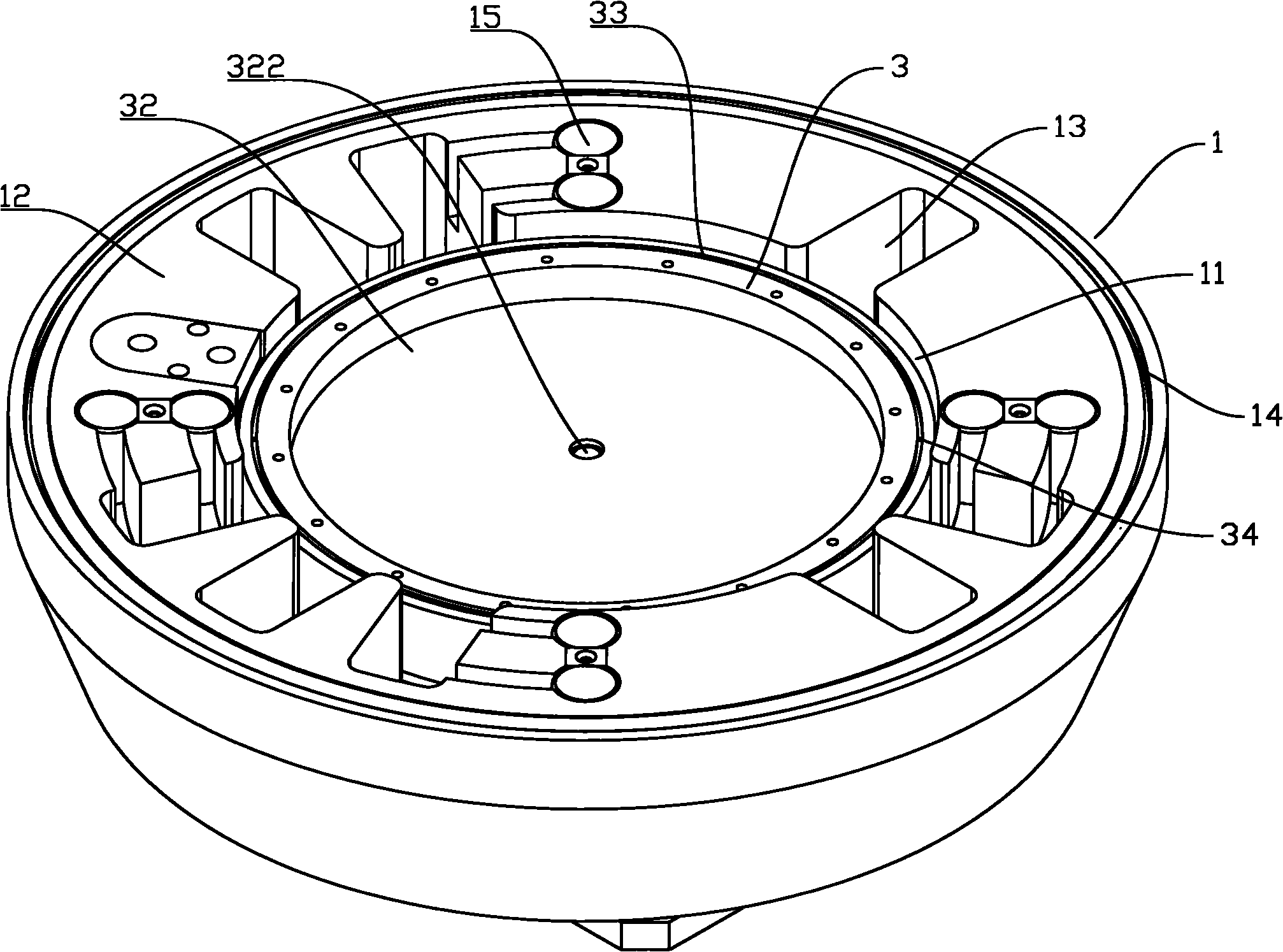
[0069]Replace the second vacuum device in Example 1 with a second gas compressor, the second gas compressor communicates with the second groove, and omit the third groove 13, the first air hole 21, the first vacuum device, the second Three air holes 23 and the third vacuum device. The second gas compressor can blow compressed gas into the second groove 32 through the second air hole, and when the wafer is placed on the upper surface of the platform 3, the second gas compressor can adjust the gas pressure in the second groove 32 . Because the gas pressure between the wafer and the film is constant, as long as the gas pressure in the second groove 32 is increased, the wafer can be pressed against the film, and because the edge of the wafer is fixed by adsorption, the wafer arches from the center and is first aligned with the film. The film is in contact, and gradually contacts the film from the center to the edge until the suction force on the edge of the wafer is released, and...

Embodiment 3

[0071] Replace the second vacuum device in Example 1 with a second gas compressor, the second gas compressor communicates with the second groove, omit the third groove 13 and the first air hole 21, and replace the third vacuum device with The third gas compressor communicates with the third air hole 23 . The gas compressor can blow compressed gas into the second groove 32 through the second air hole, and when the wafer is placed on the upper surface of the platform 3 , the second gas compressor can adjust the gas pressure in the second groove 32 . Since the gas pressure between the wafer and the film remains constant, as long as the gas pressure in the second groove 32 is increased, the wafer can be pressed against the film, and since the edge of the wafer is adsorbed and fixed, the wafer starts to arch from the center Contact the film, and gradually contact the film from the center to the edge, until the vacuum suction force that adsorbs the edge of the wafer disappears, and ...


PUM


Abstract

The invention discloses a method suitable for laminating a film for an ultrathin wafer, which is characterized in that when film lamination is carried out, a certain pressure is supplied to push a wafer to a thin film so as to adhere the thin film and the wafer together. In the method and the device suitable for laminating the film for the ultrathin wafer, provided by the invention, pressure is applied to the wafer so as to enable the wafer to be adhered to the thin film. The wafer and the thin film can be firmly adhered together through the pressure applied to the wafer. When film lamination is carried out, the thin film can supply supporting force to the wafer so as to prevent the wafer from cracking due to excessive deformation. Therefore, by using the method and the device provided by the invention for laminating the film, the problem that the ultrathin wafer cracks can be effectively avoided.

Description

technical field [0001] The invention relates to a film sticking method and a film sticking device suitable for sticking a film on an ultra-thin wafer. Background technique [0002] Usually, the circuit side of the wafer, that is, the side that completes the chip function, is called the front side, and the other side is the back side. During wafer processing, a thin film is often required. The attached film is sometimes used to protect the wafer during dicing, which is called dicing film. The attached film is sometimes a protective film in other processes. When attaching the dicing film to the wafer, attach the wafer and the frame to the dicing film together. The frame is a sheet with a through hole in the middle. The dicing film is attached to the back of the wafer. The frame and dicing film work together to protect the wafer. [0003] The simplest way to attach the dicing film is: put the wafer face down on the table, and the front side and the upper surface of the ta...

Claims


Application Information

Patent Timeline
Patent Type & Authority Applications(China)
IPC IPC(8): H01L21/02H01L21/00H01L21/687
Inventor 张明星周曙国
Owner 上海技美科技股份有限公司
Why Eureka
Try Eureka