Blade cascade for a flow engine and flow engine comprising said blade cascade

A technology of fluid machinery and blades, which is applied in the field of fluid machinery cascades and fluid machinery with such cascades, which can solve the problems of suboptimal cascades and achieve the effects of improving efficiency and easy manufacturing

Active Publication Date: 2015-01-14
MAN ENERGY SOLUTIONS SA
View PDF6 Cites 0 Cited by
  • Summary
  • Abstract
  • Description
  • Claims
  • Application Information

AI Technical Summary

Problems solved by technology

[0005] This known cascade is suboptimal

Method used


Image

  • Blade cascade for a flow engine and flow engine comprising said blade cascade
  • Blade cascade for a flow engine and flow engine comprising said blade cascade
  • Blade cascade for a flow engine and flow engine comprising said blade cascade

Examples


Embodiment Construction

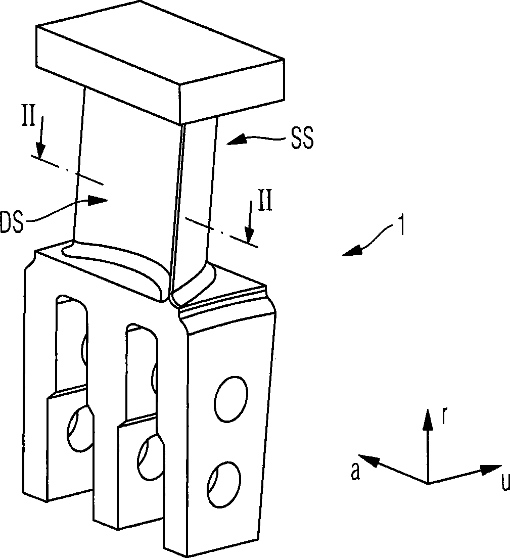
[0031] figure 1 Shown is a profiled rotor blade 1 of a cascade according to an embodiment of the invention with three-bladed pins. For orientation, the radial direction r, the circumferential direction U and the axial direction a are drawn.

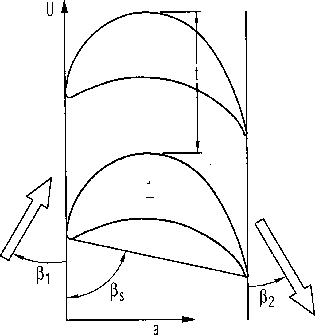
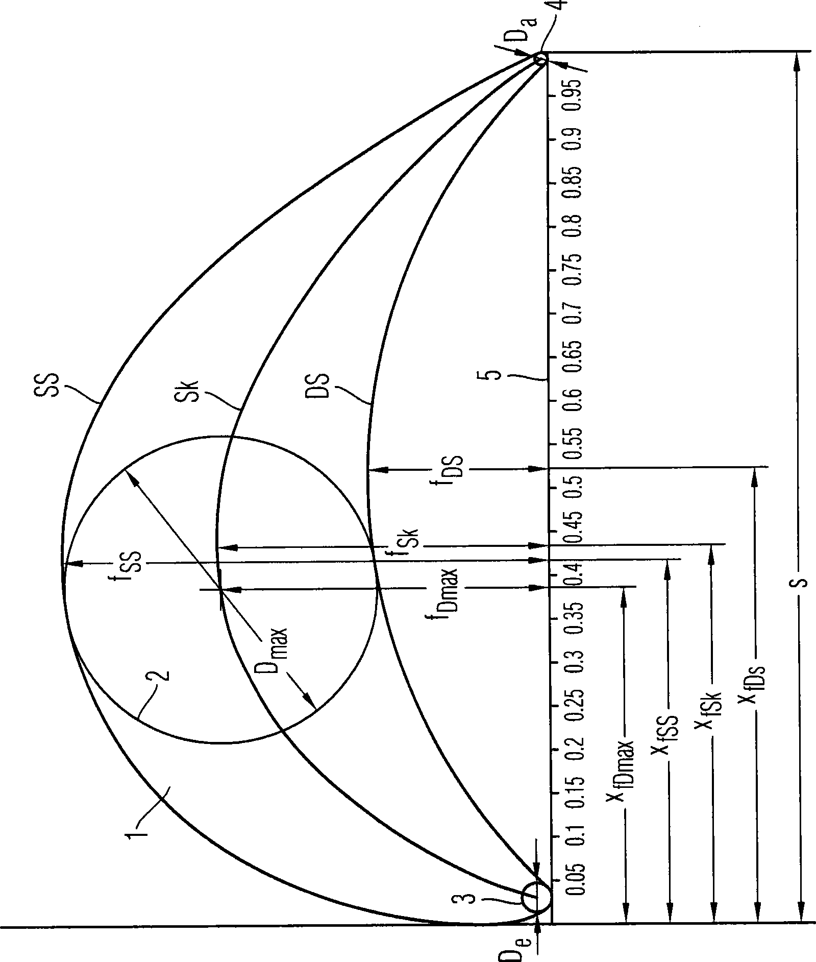
[0032] figure 2 shows the section II-II of the moving blade perpendicular to the radial direction r (compare figure 1 ), which includes the characteristic blade height and the characteristic blade circle in the double tangent system, the axis of the double tangent system and the axial direction or the circumferential direction correspondingly enclose the blade installation angle β which will be further explained below s . Here the first axis of the bitangent system (in figure 2 From left to right in the center)—the following dimension description refers to the double tangent system—parallel to the chord 5 of the moving blade 1, that is, tangent to the leading edge circle and the trailing edge circle 3, 4, the second axis (in figur...


PUM


Abstract

The invention relates to a blade cascade for a flow engine, especially a steam turbine, comprising a plurality of profiled blades, especially profiled rotor blades (1), having an intake side (SS), a pressure side (DS), a median line (Sk) and a chord length (s) between a blade leading edge and a blade trailing edge. The invention is characterized in that a quotient of the chord length (s) for a maximum height (fSS) of the intake side (SS) is between 0.53 and 0.55, a maximum height (fDS) of the pressure side (DS) is between 0.19 and 0.21, a maximum height (fSk) of the median line (Sk) is between 0.36 and 0.38, a diameter (Dmax / s) of a maximum circle extending between the intake and the pressure side is between 0.34 and 0.36, its distance between centers (xDmax / s) is between 0.37 and 0.39, its height in the center (fxDmax / s) is between 0.35 and 0.37, a diameter (De / s) of its leading edge circle (3) is between 0.025 and 0.045, a diameter (Da / s) of a trailing edge circle (4) is between 0.01 and 0.02, a radius of curvature of the intake side (SS) at a distance (XRkSS0.1) of 0.1 times the chord length (s) is between 0.39 and 0.41, a radius of curvature of the intake side (SS) at a distance (XRkSS0.75) of 0.75 times the chord length (s) is between 0.83 and 0.85, a radius of curvature of the pressure side (DS) at a distance (XRKD0.15) of 0.15 times the chord length (s) is between 0.74 and 0.76, and / or a radius of curvature of the pressure side (DS) at a distance (XRkDS0.80) of 0.80 times the chord length (s) is between 0.55 and 0.57.

Description

technical field [0001] The invention relates to a blade cascade for a fluid machine, in particular a steam turbine, comprising a plurality of profiled blades, in particular profiled moving blades (Laufschaufel) comprising a suction side, a pressure The invention also relates to a fluid machine with such a blade cascade. Background technique [0002] In fluid machines, such as steam turbines, in particular, a compressible fluid, such as steam, is diverted through one or more cascades and thereby exerts a force on the cascades. If the cascade is active, the fluid drives the moving cascade and thereby performs work. In order to deflect the flow, a fixed so-called guide cascade can also be provided, in particular above the downstream rotor blades. [0003] For today's cascades, in particular for moving blades of steam turbines, significant fluid acceleration occurs in the flow channel defined between the pressure side of the blade and the suction side of the circumferentially ...

Claims


Application Information

Patent Timeline
Patent Type & Authority Patents(China)
IPC IPC(8): F01D5/14
CPCF01D5/141
Inventor G·纽曼J·加茨克U·哈贝克M·A·施沃茨
Owner MAN ENERGY SOLUTIONS SA
Why Eureka
Try Eureka