Bone bridging clamp

A technology for connecting fixtures and connecting parts, used in the field of medical devices, can solve problems such as secondary injury and affect bone healing, and achieve the effects of fast postoperative healing and reduced surgical difficulty and risk.

Inactive Publication Date: 2011-06-08
沈军
View PDF0 Cites 2 Cited by
  • Summary
  • Abstract
  • Description
  • Claims
  • Application Information

AI Technical Summary

Problems solved by technology

The disadvantage is that when the steel nail and the steel plate are used to reset the broken bone, the steel nail must be driven into the bone, which will cause secondary damage and affect the healing of the bone.

Method used


Image

  • Bone bridging clamp
  • Bone bridging clamp

Examples


Embodiment Construction

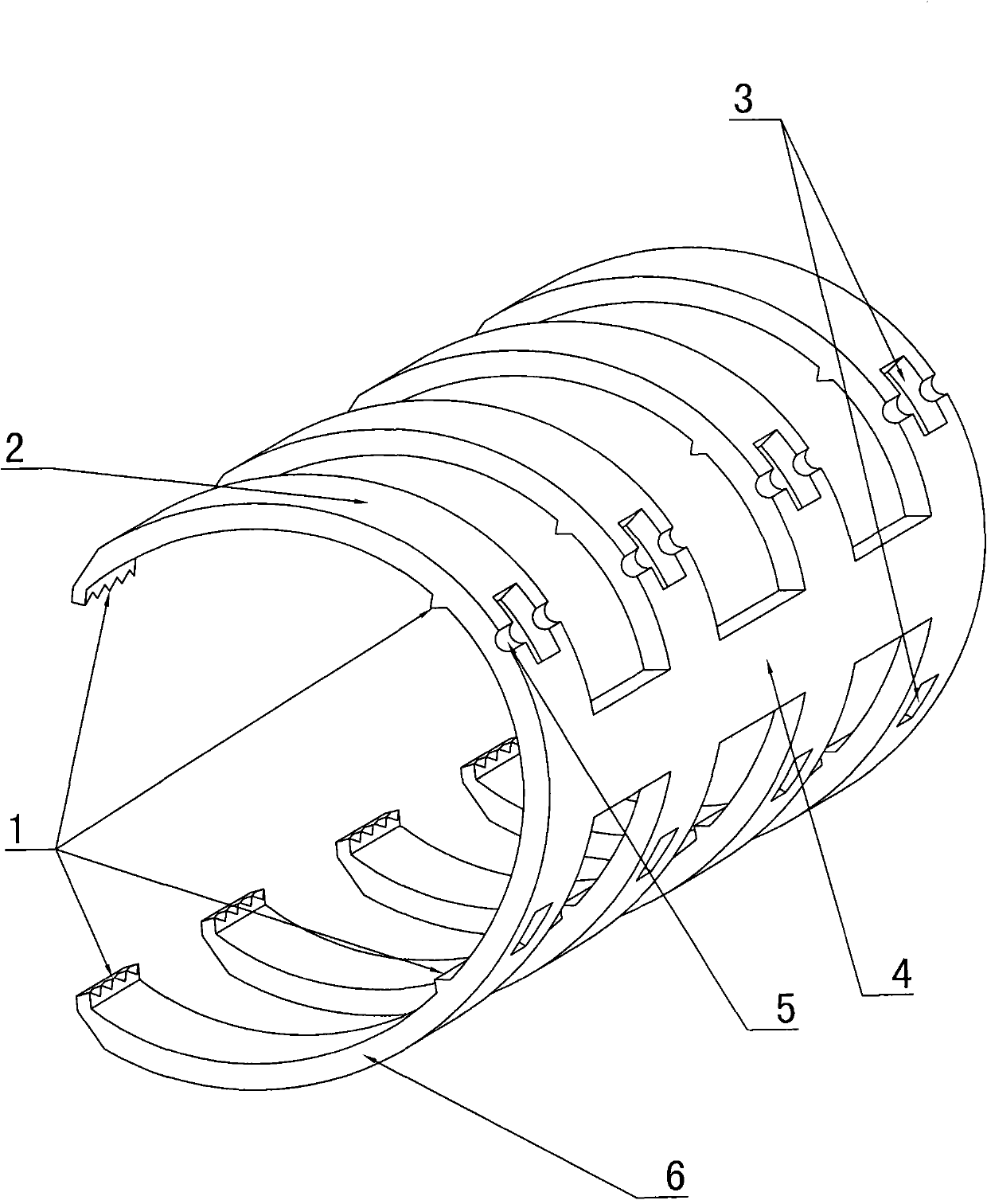
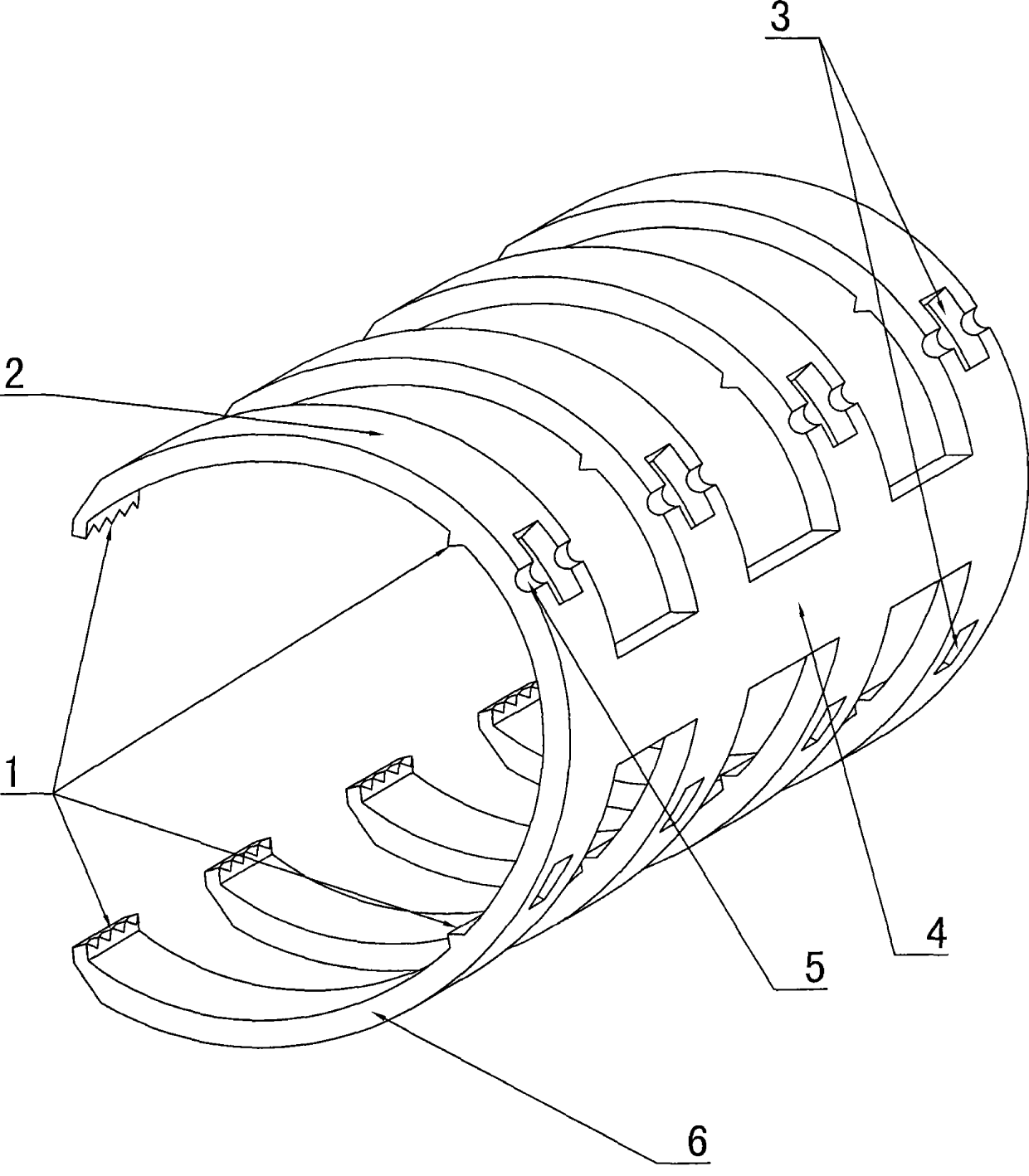
[0010] A bone connection fixture of the present invention includes an upper clamp arm 1 and a lower clamp arm 6 made of memory alloy material, the upper clamp arm 1 and the lower clamp arm 6 are integrally connected in a C shape, and the upper clamp arm and the lower clamp arm There are at least two groups of arms, and the adjacent two groups are connected as a whole through the connecting part 4. Each upper clamping arm and lower clamping arm are respectively provided with two groups of ridge-shaped protrusions 1 for clamping long bones. The ridge-shaped protrusions 1 are distributed in a rectangular shape, and the ridge-shaped protrusions are distributed in a tooth shape in the length direction. A clamp hole 3 is respectively provided on the upper clamp arm 1 and the lower clamp arm 6. The upper clamp arm 1 or the lower clamp arm 2 There is an unloading groove 5 at the upper clamp hole 2 position.


PUM


Abstract

The invention discloses a bone bridging clamp in the field of medical equipment, which comprises at least two groups of upper clamping arm and lower clamping arm. Each upper clamping arm and each lower clamping arms are made of memory alloy materials and are connected integrally to form a C shape, connection parts of two adjacent groups are connected into a whole, each upper clamping arm and the each lower clamping arm are respectively provided with two groups of crestiform protrusions used for clamping long bones, and the crestiform protrusions are distributed rectangularly. The bone bridging clamp is used for fixing fractured bones and has the advantages of small damage to bones and convenience for operation, and patients can heal rapidly.

Description

technical field [0001] The invention relates to a medical device, in particular to a medical device for bone setting. Background technique [0002] In the prior art, when a human bone breaks, steel nails and steel plates are often used for fixation. During the operation, holes are drilled in the steel plate in advance, and the skin and flesh are cut to expose the bone. , fix and reset the broken bone, and then suture the skin and flesh; when the bone grows well, another operation will be performed to remove the steel nails and steel plates on the bone. Its shortcoming is: when the steel nail and the steel plate reset the broken bone, the steel nail will be driven into the bone, which will cause secondary damage and affect the healing of the bone. Contents of the invention [0003] The technical problem to be solved by the present invention is to provide a bone connection jig, which can easily reset the fracture site, facilitate the operation, cause little damage to the hu...

Claims


Application Information

Patent Timeline
Patent Type & Authority Applications(China)
IPC IPC(8): A61B17/82
Inventor 沈军
Owner 沈军
Why Eureka
Try Eureka