
Spiral type cooling cavity of pump

A spiral type, cooling chamber technology, applied to pumps, parts of pumping devices for elastic fluids, pump components, etc., can solve the problems of easy vaporization of dynamic and static sealing surfaces, seal failure, dry friction, etc., and achieve improved working conditions conditions, reduce the pressure of the sealing chamber, and reduce the effect of the temperature of the sealing chamber

Inactive Publication Date: 2011-06-08
KSB SHANGHAI PUMP
View PDF0 Cites 2 Cited by
  • Summary
  • Abstract
  • Description
  • Claims
  • Application Information

AI Technical Summary

Problems solved by technology

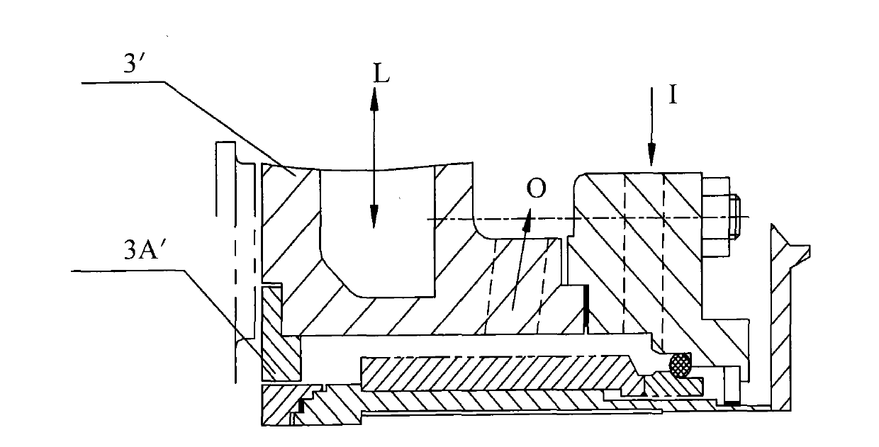
from figure 1 It can be seen that the axial length of the cooling chamber is short, and the axial length of the sealing chamber 3A' is also short. In actual use, once the temperature of the high-temperature circulating water in the pump medium is high, the liquid in the sealing chamber will appear temperature If the temperature is too high (generally limited to within 1000C), the pressure is also high at this time. The consequence is that the dynamic and static sealing surfaces of the mechanical seal parts are easy to vaporize and cause dry friction, which makes the seal invalid, thus shortening the life of the mechanical seal parts.
For this reason, when the temperature of the medium in the pump is high, some additional auxiliary measures must be added to achieve the purpose of heat exchange, which will cost more water resources and power consumption.

Method used


Image

  • Spiral type cooling cavity of pump
  • Spiral type cooling cavity of pump
  • Spiral type cooling cavity of pump

Examples


Embodiment Construction

[0026] The specific implementation manners of the present invention will be described in detail below in conjunction with the accompanying drawings of the embodiments.

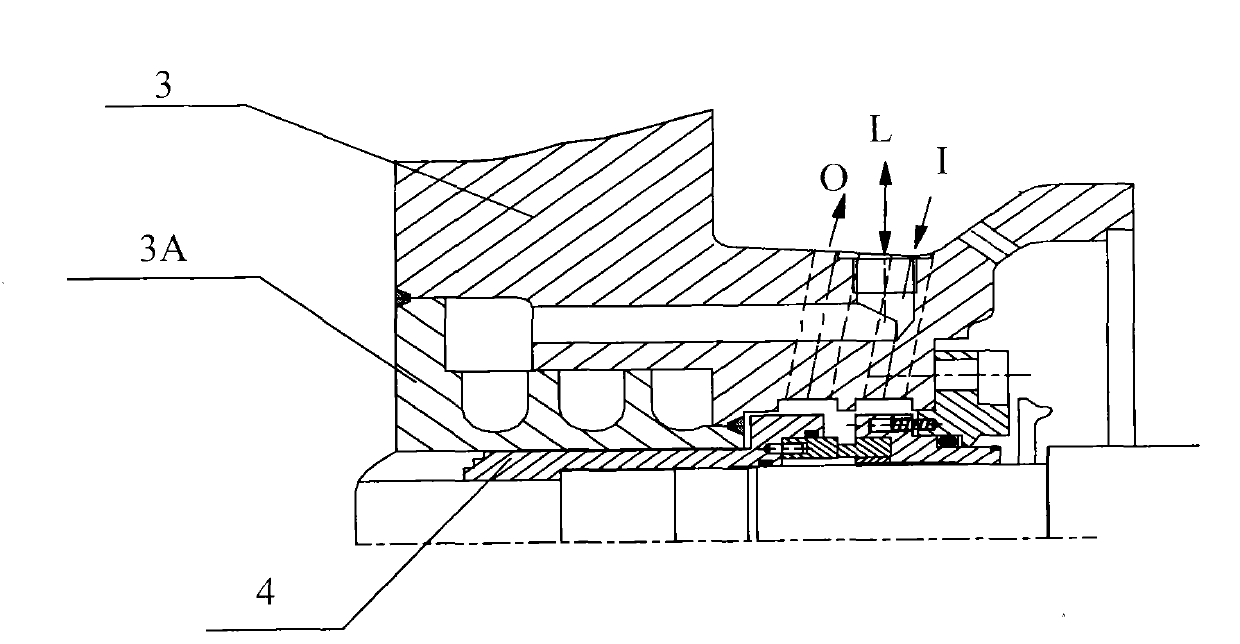
[0027] see figure 2 , figure 2 It is a schematic diagram of the structural principle of the spiral cooling cavity of the present invention.

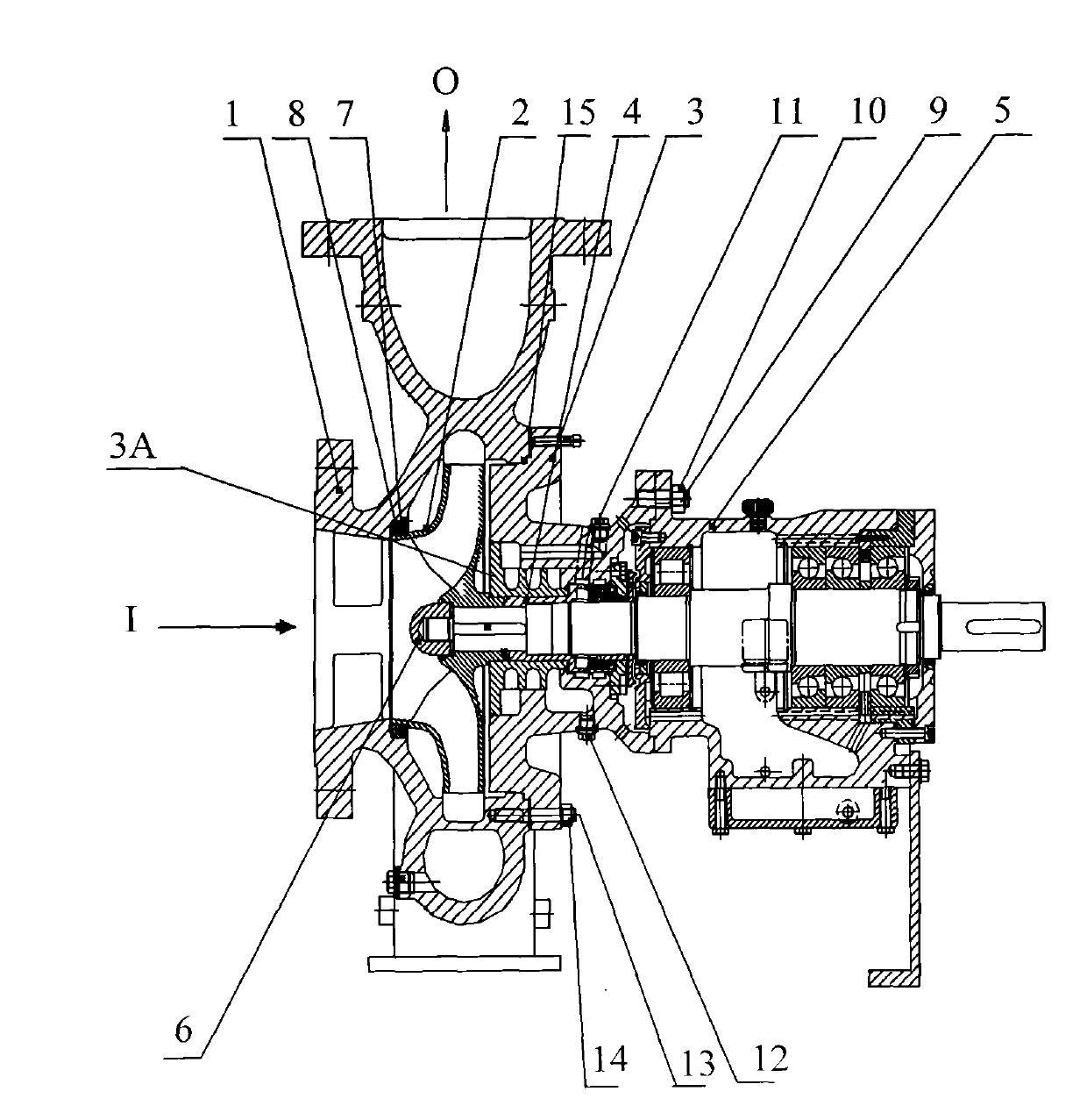
[0028] figure 2 The cooling water indicated by L enters and exits, the circulating water indicated by I enters, and the circulating water indicated by 0 exits. The cooling cavity of the present invention is arranged on the pump cover 3 of the pump, and is formed by welding the screw type sealing cavity 3A and the pump cover 3, and the screw type sealing cavity 3A is processed into a single helical cooling water passage ( Figure 5 As shown), as shown in the figure, the axial stroke of the spiral channel is longer, and the axial length between the spiral seal cavity 3A and the moving ring sleeve in the mechanical seal component 4 is also longer. In actual use, sinc...


PUM


Abstract

The invention relates to a spiral type cooling cavity of a pump, belonging to the field of cooling cavities and solving the problem that the heat exchange conductivity of a cooling cavity of the traditional pump is limited to influence the service life of a mechanical sealing part of the traditional pump. The spiral type cooling cavity provided by the invention is arranged on a pump cover of a pump and comprises a spiral type sealing cavity and the pump cover, wherein the a spiral type sealing cavity comprises a cavity bottom and a concentric spiral groove body which is integrally formed at the cavity bottom; a single-spiral cooling water channel is formed by welding the cavity bottom and the outer surface of the concentric spiral groove body with the pump cover and is internally provided with a cylindrical through hole; and one end of the single-spiral cooling water channel is connected with a cooling water inlet, and the other end is connected with a cooling water outlet. Compared with the traditional cooling cavity, the spiral type cooling cavity has a cooling length lengthened by approximately 8 times and a cooling area enlarged by approximately 2 times, thereby the conditions for the operating condition of the mechanical sealing part of the pump are improved; and in addition, the spiral type cooling cavity can also achieve the purpose of heat exchange, without being additionally provided with auxiliary measures, even when the temperature of a hot fluid medium inside the pump exceeds 250 DEG C, thereby the operating cost is reduced.

Description

technical field [0001] The invention relates to a cooling chamber, in particular to a pump spiral cooling chamber. Background technique [0002] The cooling chamber of the high-temperature hot water circulating pump is used to cool the shaft seal chamber to meet the conditions of use of the mechanical seal. The heat transfer conductivity of the cooling chamber of the traditional high-temperature hot water circulation pump is limited, that is, the temperature of the hot water in the pump at the front side of the shaft seal chamber can only reach within 250 °C. [0003] When the hot water temperature exceeds 250°C, the pump must add some additional auxiliary measures, such as reducing the cooling water inlet temperature, increasing the cooling water volume and pressure, in order to achieve the purpose of heat exchange and meet the requirements of the mechanical seal. [0004] see figure 1 , figure 1 It is a schematic diagram of a traditional cooling chamber structure. [0...

Claims


Application Information

Patent Timeline
Patent Type & Authority Applications(China)
IPC IPC(8): F04D29/58
Inventor 闵思明
Owner KSB SHANGHAI PUMP
Learn More