Rotary-distribution and membrane flash specific gravity differential concentration method

A technology with poor specific gravity and flash evaporation, which is applied in the field of concentration, can solve problems such as high steam energy consumption, foaming and overflow, and difficult separation of liquid and vapor, so as to improve work efficiency, reduce frictional resistance, and solve foaming and overflow.

Active Publication Date: 2011-06-15
中国船舶重工集团公司第七〇三研究所
View PDF3 Cites 3 Cited by
  • Summary
  • Abstract
  • Description
  • Claims
  • Application Information

AI Technical Summary

Problems solved by technology

[0003] The purpose of the present invention is to solve the problems of high steam energy consumption in the existing concentration method, the heat-labile components are easily destroyed, and

Method used


Image

  • Rotary-distribution and membrane flash specific gravity differential concentration method
  • Rotary-distribution and membrane flash specific gravity differential concentration method
  • Rotary-distribution and membrane flash specific gravity differential concentration method

Examples


specific Embodiment approach 1

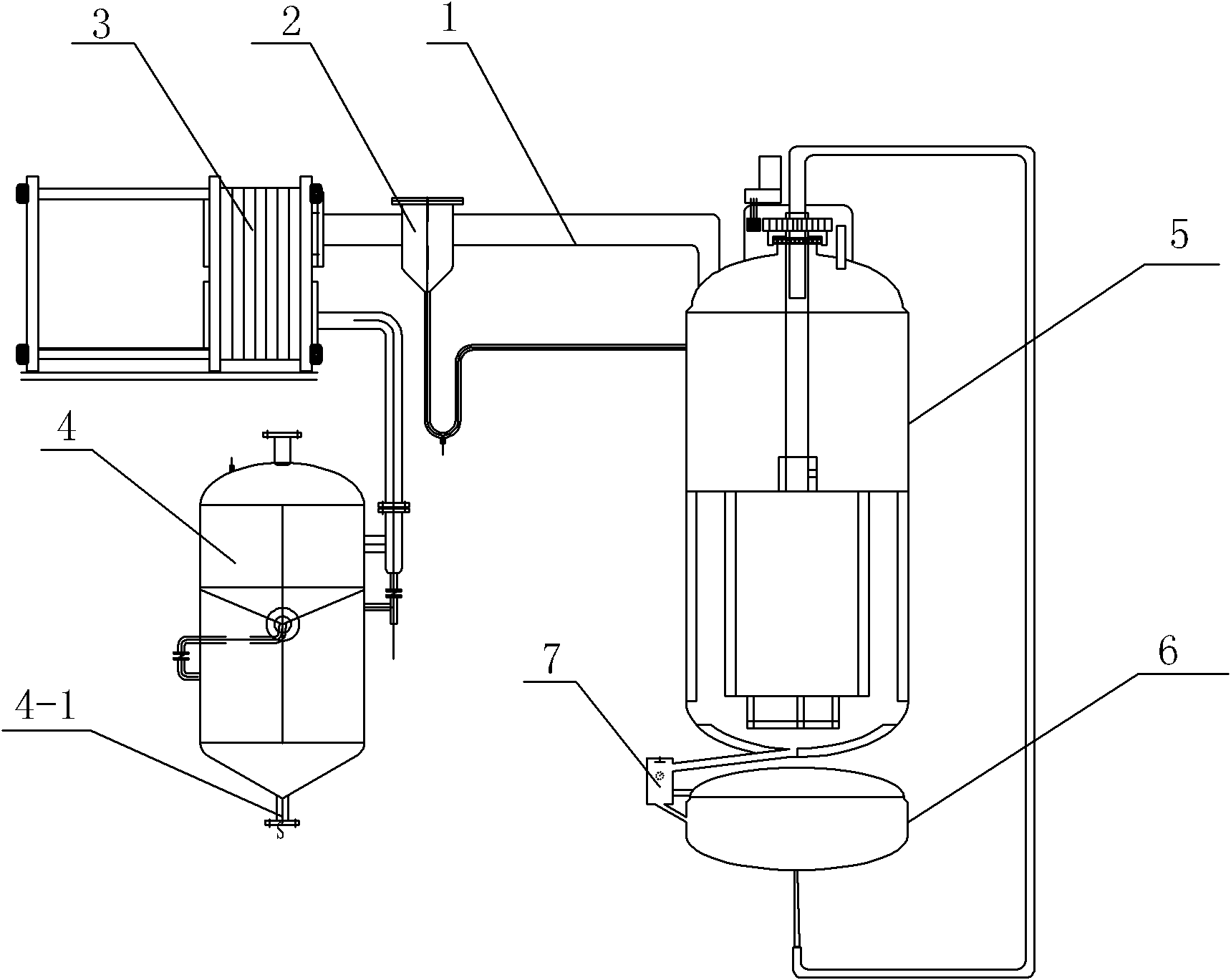
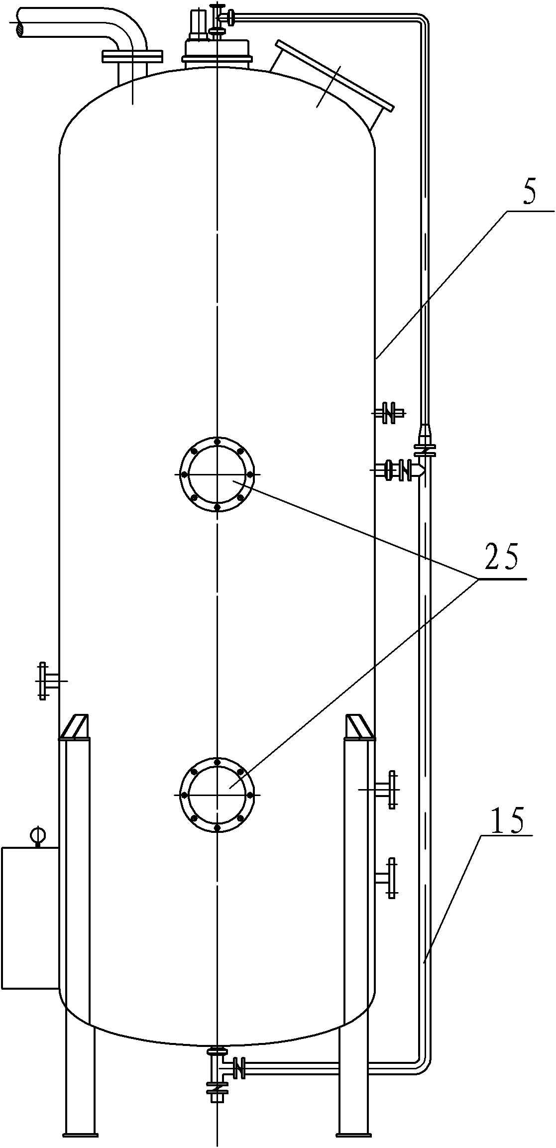
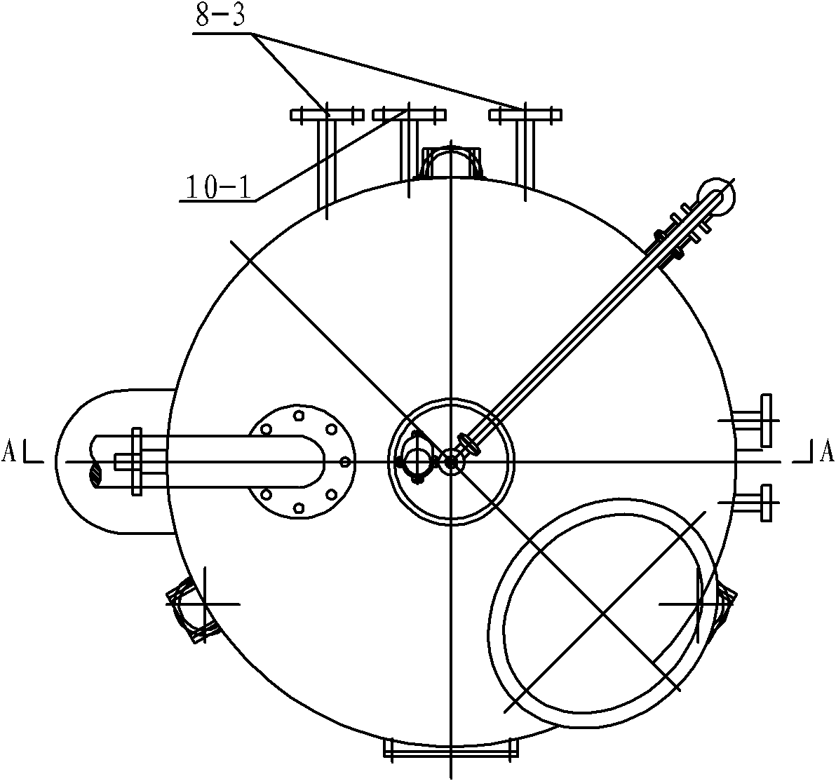
[0007] Specific implementation mode one: the following combination Figure 1-Figure 8 Describe this embodiment in detail, the rotary distribution of this embodiment, the membrane flash specific gravity type concentrator comprises evaporation vapor collector 1, vapor-liquid separator 2, condenser 3 and recovery liquid collector 4, the bottom of recovery liquid collector 4 There is a recovery liquid discharge port 4-1, one end of the vapor collection pipe 1 communicates with the inlet of the vapor-liquid separator 2, the outlet of the vapor-liquid separator 2 communicates with the inlet of the condenser 3, and the outlet of the condenser 3 end communicates with the inlet end of the recovery liquid collector 4, and it is characterized in that the concentrator also includes a distribution device, an evaporation tank 5, a collection tank 6, a density measuring device 7, an intermediate jacket 8, an outer jacket 9, and a bottom jacket 10. Condensed water discharge pipe 11, discharge...

specific Embodiment approach 2

[0011] Specific embodiment two: the method of this embodiment comprises the following steps: Step 1, vacuumize the evaporator 5 through the vacuum port 5-1, so that the vacuum degree in the evaporator 5 is 0.7-0.95Mpa; Step 2, put the cloth The device starts, and simultaneously feeds steam into the second steam inlet 8-1 of the two intermediate jackets 8, the first steam inlet 9-1 of the outer jacket 9, and the third steam inlet 10-1 of the bottom jacket 10, so that The temperature in the evaporator 5 is controlled between 50-80°C, so that the temperature of the middle jacket 8, the outer jacket 9 and the bottom jacket 10 is controlled between 100-135°C; step 3, open the main feed valve 26 And sub-feed valve 27, the feed liquid continuously enters into the distribution device through the main feed pipe 14 and the first sub-feed pipe 15, and the distribution device rotates and distributes the feed liquid in the middle jacket 8, the outer jacket 9 and the bottom jacket On the wa...

specific Embodiment approach 3

[0012] Specific embodiment three: the gas after the feed liquid evaporates in the step three of the present embodiment enters the condenser 3 to cool after passing through the evaporation vapor collection pipe 1 and the gas-liquid separator 2 under the action of vacuum, and the recovered liquid of the cooled gas enters the In the recovery liquid collector 4. Other method steps are the same as those in the first embodiment.


PUM


Abstract

The invention discloses a rotary-distribution and membrane flash specific gravity differential concentration method, relating to a concentration method. The invention aims at solving the problems of high steam energy consumption, easy damage of heat-labile components, and froth over caused by difficult separation of liquid from steam in the traditional concentration method. The method comprises the following steps: 1, an evaporating tank is vacuumized through a vacuumizing hole; 2, a distributing device is started to simultaneously introduce steam into second steam inlets of two intermediate jackets, a first steam inlet of an outer jacket and a third steam inlet of a bottom jacket; 3, a total feeding valve and a branch feeding valve are opened, a feed solution enters in the distributing device, the distributing device distributes the feed solution onto the walls of the intermediate jackets, the outer jacket and the bottom jacket for rapid evaporation, i.e. the feed solution is concentrated; and 4, the concentrated feed solution enters a density measurer under the action of gravity through an outlet at the bottom of the evaporating tank, and enters a collecting tank after the density of the concentrated feed solution is detected. The invention is used for concentrating the feed solution.

Description

technical field [0001] The present invention relates to a concentration method. Background technique [0002] The common deficiency of existing vacuum decompression concentration methods, falling film evaporation methods, external circulation evaporation methods, double-effect falling film evaporation methods, double-effect external circulation evaporation methods, and forced circulation evaporation methods is that the consumption of steam energy is high. , Continuous heating cycle and long cycle heating time, the heat-labile components may be destroyed, and the liquid and vapor are not easy to separate, resulting in foaming and overflowing. Contents of the invention [0003] The purpose of the present invention is to solve the problems of high steam energy consumption in the existing concentration method, the heat-labile components are easily destroyed, and the liquid vapor is not easy to separate, resulting in foaming and overflowing, and to provide a rotary distribution...

Claims


Application Information

Patent Timeline
IPC IPC(8): B01D1/22
Inventor 刘庆阁明维国王景义唐晓彬刘亮亮王翠鸣赵旭
Owner 中国船舶重工集团公司第七〇三研究所
Why Eureka
Try Eureka