Sedimentation type soil-liquid separator

A solid-liquid separation and sedimentation technology, which is applied to the feeding/discharging device of the settling tank, the use of liquid separating agent, the settling tank, etc., can solve problems such as disturbance and lowering the settling separation efficiency of the solid-liquid separation device

Active Publication Date: 2011-06-15
卓卫民
View PDF4 Cites 8 Cited by
  • Summary
  • Abstract
  • Description
  • Claims
  • Application Information

AI Technical Summary

Problems solved by technology

[0004] In this technology, the screw conveyor is exposed at the bottom of the settling chamber, so that when the spiral blades of the screw conveyor rotate rapidly, it will disturb the adsorption liquid in the se

Method used


Image

  • Sedimentation type soil-liquid separator
  • Sedimentation type soil-liquid separator
  • Sedimentation type soil-liquid separator

Examples


Embodiment 1

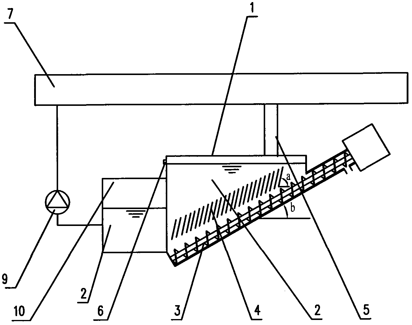
[0048] Such as figure 1 Shown is the settling type solid-liquid separation device described in this embodiment, comprising: a settling water tank 1, a liquid inlet tank is arranged on the top of the settling water tank 1, and the width of the liquid inlet tank is the width of the settling water tank 1 0.8 times the width;

[0049] A liquid outlet is provided on one side of the settling water tank 1 and near the top;

[0050] A circulating water tank 10 is also provided on the side where the settling water tank is provided with a liquid outlet, and the adsorption liquid flowing out from the liquid outlet 6 enters the circulating water tank 10, and the circulating water tank 10 passes through a circulating pump and a wet dust collector. 7-phase connection;

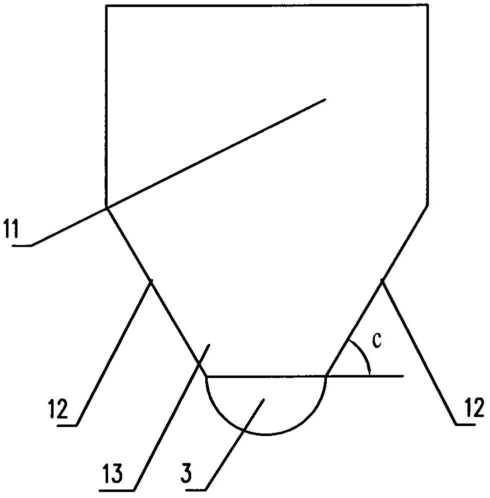
[0051] In the settling water tank 1, a screw conveyor 3 is arranged at the bottom of the settling water tank 1. The height of the screw conveyor 3 gradually increases along the conveying direction of the mud, and the angle...

Embodiment 2

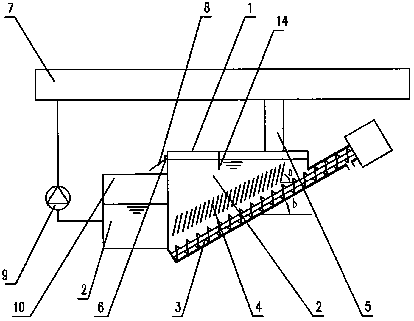
[0059] Such as figure 2 Shown is the sedimentation type solid-liquid separation device described in this embodiment. Compared with Embodiment 1, the width of the liquid inlet tank of the solid-liquid separation device in this embodiment is 0.6 of the width of the settlement tank 1 times, as an optional embodiment, the width of the liquid inlet tank of the present invention can also be set to any size that allows the adsorption liquid 2 to enter the settling water tank 1;

[0060] In the present embodiment, the height of the screw conveyor 3 gradually increases along the conveying direction of the mud, the angle b between the screw conveyor 3 and the horizontal plane is 20°, and the screw shaft diameter of the screw conveyor 3 is 100mm. The diameter of the helical blade on the described helical shaft is 5 times of the diameter of the helical shaft, and the pitch of the helical blade is equal to the diameter of the helical blade. The included angle b can also be set to other a...


PUM


Abstract

The invention provides a sedimentation type soil-liquid separator, which comprises: a sedimentation water box, wherein a liquid inlet tank is arranged on the top of the sedimentation water box, a liquid outlet is formed on one side of the sedimentation water box and close to the top of the sedimentation water box, and a spiral conveyer is arranged in the sedimentation water box and positioned at the bottom of the sedimentation water box. The sedimentation type soil-liquid separator is characterized in that: a plurality of guide plates are arranged above the spiral conveyor in an inclined way relative to the plane; and a circular water box is arranged at the water outlet of the sedimentation water box. In the invention, by arranging the guide plates in the soil-liquid separator and combining with the intermittent working mode of the spiral conveyor, the perturbation of the absorption liquid caused by the spiral conveyor is prevented from being transmitted to the upper parts of the guide plates, and the phenomenon that dust particles float upwards and overflow from the sedimentation water box due to the disturbance of the spiral conveyor is avoided.

Description

technical field [0001] The invention relates to a solid-liquid separation device, in particular to a device for solid-liquid separation using a sedimentation method, which can realize the recycling of adsorption liquid in a wet dust collector. Background technique [0002] Wet dust removal refers to the use of water or other liquids in contact with dust-containing gas to absorb impurities in the gas. During the above-mentioned treatment process, when dust particles meet sprayed water droplets, water films or wet devices, wetting, Coagulation, diffusion and sedimentation, etc., are separated from the gas to achieve the purpose of purifying the gas. Wet dust removal has the advantages of low investment, simple operation, small footprint, simultaneous purification of harmful gases, cooling and humidification of dusty gases, etc. It is especially suitable for the purification of high temperature, high humidity and explosive dangerous gases. However, since wet dust removal uses ...

Claims


Application Information

Patent Timeline
IPC IPC(8): B01D21/02B01D21/24B01D47/00
Inventor 卓卫民左丽卓宇轩袁儒正张亮魏稳高科熊一峰滕明蒋炎炎张峰
Owner 卓卫民
Why Eureka
Try Eureka