Mixing stirring machine

A technology for mixers and mixing tanks, which is applied to mixers, mixer accessories, mixers with rotating stirring devices, etc., and can solve problems such as uneven thickness of fillings, difficulty in taking out, and poor fluidity

Active Publication Date: 2011-06-15
DONGGUAN XUJI FOODSTUFF
View PDF11 Cites 7 Cited by
  • Summary
  • Abstract
  • Description
  • Claims
  • Application Information

AI Technical Summary

Problems solved by technology

[0002] The food mixers currently on the market have a certain degree of static dead angle when the material is stirred in the barrel, especially the mixing of shortening, milk powder, and sugar powder, which has poor fluidity. If there is a static dead angle, it can be mixed by stirring. The specific gravity of the fil

Method used


Image

  • Mixing stirring machine
  • Mixing stirring machine

Examples


Embodiment 1

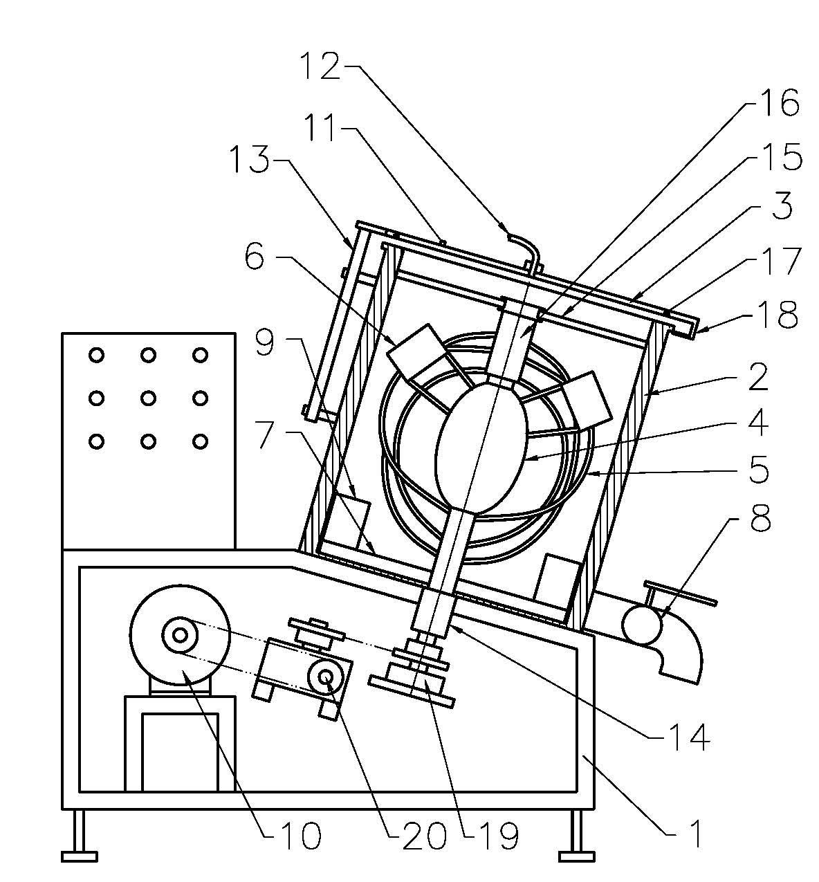
[0022] Embodiment 1, see figure 1 ,

[0023] A mixing mixer, which comprises a mixing tank, a stirring device, a driving mechanism and a frame 1, the stirring device is arranged in the mixing tank, the mixing tank is arranged on the frame 1, and the stirring device includes a stirring ball 16 and a scraper at the bottom of the bucket 7 and the side scraper 9, the side scraper 9 is arranged at the end of the bucket bottom scraper 7, the bucket bottom scraper 7 is arranged at the bottom of the mixing bucket, the stirring ball 16 and the bucket bottom scraper 7 are connected with the driving mechanism, and the mixing ball 16 includes a sealing ball 4 surrounded by a steel wire 5 , and a lower pressing plate 6 is arranged on the steel wire 5 .

[0024] The function of the sealing ball 4 is to push and spread the material statically accumulated in the center to the surrounding when stirring. The outer periphery of the sealing ball 4 is a stirring steel wire 5, which is used to st...

Embodiment 2

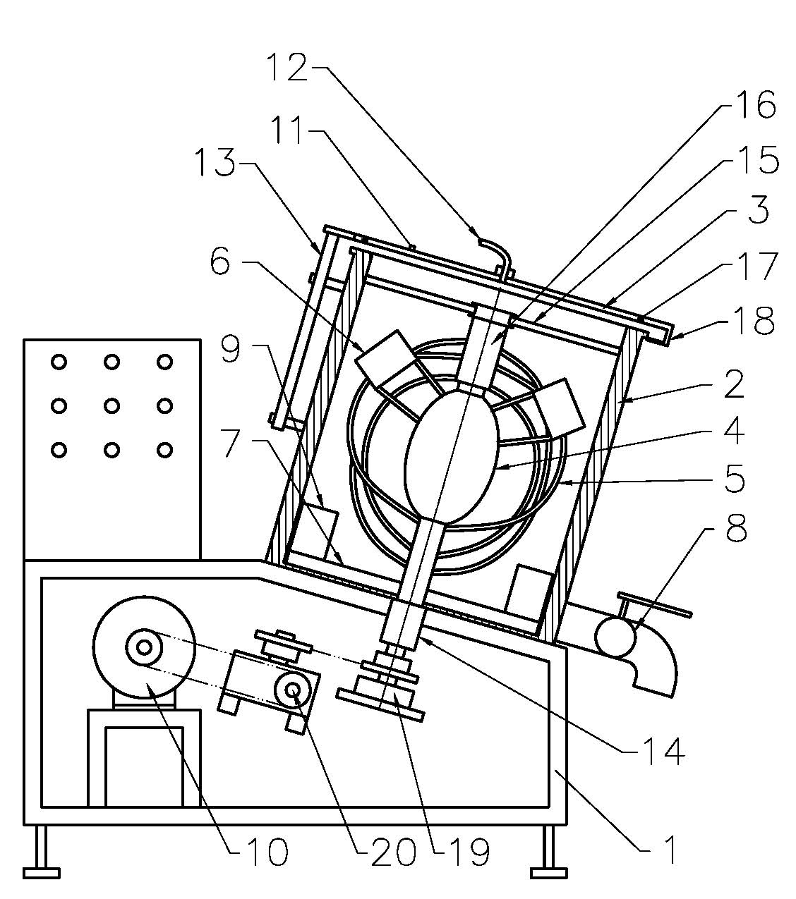
[0034] Embodiment 2, see figure 1

[0035] A kind of mixing mixer, it comprises mixing tank, stirring device and frame 1, and stirring device is arranged in the mixing tank, and mixing tank is arranged on frame 1, and described stirring device comprises stirring ball 16 and bucket bottom scraper 7 and side The scraper 9 and the side scraper 9 are arranged at the end of the scraper 7 at the bottom of the barrel, the scraper 7 at the bottom of the barrel is arranged at the bottom of the mixing barrel, the stirring ball 16 and the scraper 7 at the bottom of the barrel are connected with the driving mechanism, and the stirring ball 16 includes a sealing Steel wire strips 5 interwoven in different directions are arranged around the ball 4 and the sealing ball 4 , and a lower pressing plate 6 is arranged on the steel wire strips 5 .

[0036] The function of the sealing ball 4 is to push and spread the material statically accumulated in the center to the surrounding when stirring...


PUM


Abstract

The invention relates to the technical field of mixing stuffing and sizing agent, particularly to a mixing stirring machine used in the field of food processing. The invention provides a mixing stirring machine which is high in stirring efficiency, has good stirring effect and is simply and conveniently used. The mixing stirring machine comprises a stirring barrel, a stirring device, a driving mechanism and a frame, wherein the stirring device is arranged in the stirring barrel; the stirring barrel is arranged on the frame; the stirring device comprises a stirring ball, a barrel bottom scrapping plate and a side scrapping plate; the side scrapping plate is arranged on the end part of the barrel bottom scrapping plate; the barrel bottom scrapping plate is arranged on the bottom of the stirring barrel; the stirring ball and the barrel bottom scrapping plate are connected to the driving mechanism; the stirring ball comprises a sealing ball; steel wire strips are wound around the sealing ball; and a lower pressing plate is arranged on the steel wire strips. The mixed materials are turned up and down, left and right, under the action of the lower pressing plate on the stirring ball, the barrel bottom scrapping plate and the side scrapping plate. The effects of uniformly mixing and consistent density are achieved by continuously cutting through the steel wire strips. The operation is convenient and practical, the structure is simple and the cost is low.

Description

technical field [0001] The invention relates to the technical field of stuffing and slurry mixing, in particular to a mixer in the food processing industry. Background technique [0002] The food mixers currently on the market have a certain degree of static dead angle when the material is stirred in the barrel, especially the mixing of shortening, milk powder, and sugar powder, which has poor fluidity. If there is a static dead angle, it can be mixed by stirring. The specific gravity of the fillings is different, there are small crystallized particles of shortening, milk powder, and sugar powder, the fillings are uneven in thickness, not delicate, and the taste is extremely bad. It is difficult to take out, because of poor fluidity, it is impossible to flow out automatically, and it is inconvenient to operate. Contents of the invention [0003] The object of the present invention is to provide a mixing mixer with high stirring efficiency, good effect and easy handling in...

Claims


Application Information

Patent Timeline
IPC IPC(8): B01F7/02B01F15/00B01F15/02
Inventor 金棋
Owner DONGGUAN XUJI FOODSTUFF
Why Eureka
Try Eureka