Terminal post riveting device and breaking tool

A technology of riveters and poles, which is applied in the direction of manufacturing tools, metal processing, metal processing equipment, etc., can solve the problems of easy loose connection of pole bolts, poor electrical contact, etc., to solve poor electrical contact, facilitate maintenance, and avoid stress Increased effect

Inactive Publication Date: 2012-03-28
MEISHAN HENGSHENG MECHANICAL EQUIP
View PDF0 Cites 2 Cited by
  • Summary
  • Abstract
  • Description
  • Claims
  • Application Information

AI Technical Summary

Problems solved by technology

[0003] The pole rivet riveter and the cutting tool proposed by the present invention are to solve the problem that the existing pole bolt connection is easy to loose and cause poor electrical contact
At the same time, it also provides a cutting tool after riveting to solve the problem of convenient maintenance of pole rivets

Method used


Image

  • Terminal post riveting device and breaking tool
  • Terminal post riveting device and breaking tool

Examples


Embodiment 1

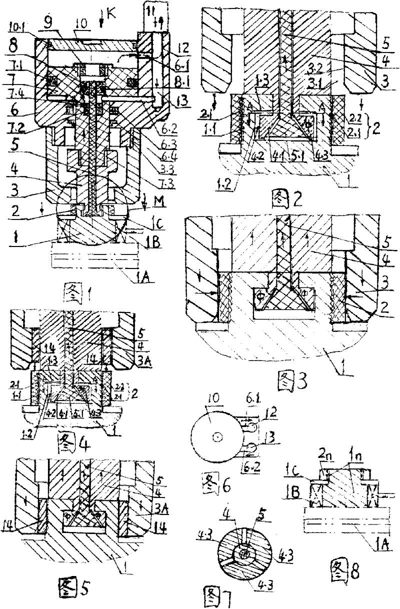
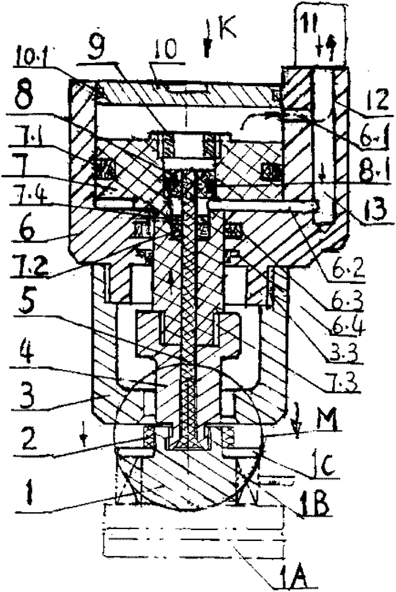
[0017] Example 1: Riveter for pole rivets figure 1 , figure 2 , image 3 , Image 6 and Figure 7 .

[0018] Pole rivet structure: see figure 1 , figure 2 , the outer circumference of the upper end of the pole 1 of the electric vehicle storage battery 1A is an outer ring groove 1.1, and the outer ring groove 1.1 is in interference fit with the inner ring groove 2.1 of the inner hole of the collar 2; a T-shaped groove 1.2 is opened in the center of the upper plane of the pole, And form step 1.3. Riveter structure: see figure 2 , a strut 5 is arranged at the center of the cylinder body 6, and the gripping rod 4 is tightly sleeved on the outside of the strut. The included angle Φ between the side and the radial direction is selected as 8°. The inner hole 4.1 at the bottom end of the grab bar is consistent with the trumpet-shaped body at the bottom end of the strut bar, and the outer circumference 4.2 at the bottom end of the grab bar is consistent with the T-shaped ...

Embodiment 2

[0022] Embodiment 2: breaking tool, see figure 1 , Figure 4 Figure 5 Image 6 Figure 7 . The pole rivet breaking tool is identical to Embodiment 1 except for the following features:

[0023] 1) see Figure 4 , Figure 5 In this embodiment, the outer casing 3A of the cutting tool is formed by installing two axial feed cutter heads 14 evenly distributed along the circumferential direction on the inner circle of the outer casing 3 of the pole rivet riveter. Cutting process: see figure 1 and Figure 4 , the cutting process is the same as that of the riveting process, the up and down movements of the oil cylinder, the support rod, the grip rod, and the jacket are the same, except that during riveting, the upward movement of the support rod and the downward movement of the jacket is to squeeze the collar 2, while the riveting is In the cutting collar. See Figure 4 , the initial position of the breaking tool, the collar exists. See Figure 5 , the position where th...


PUM


Abstract

The invention relates to a terminal post riveting device and a breaking tool. A strut is arranged at the center of a cylinder body; a grabbing rod is tightly sheathed outside the strut; the bottom ends of the strut and the grabbing rod are inserted in a T-shaped groove formed on the upper plane of the terminal post of a battery; the strut has a horn-shaped bottom end; and the bottom end of the grabbing rod is a three-flap centripetal clamping body matched with the strut and the T-shaped groove. The oil cylinder consists of a cylinder body on the upper end, a jacket on the lower end, wherein the cylinder body is connected with the jacket through threads; a strut piston fixed with the upper end of the strut and a rivet piston at the periphery are arranged in the cylinder body; and the lower end of the rivet piston is connected with the grabbing rod through threads to form a single-oil-path double-piston structure. When the oil cylinder is started, the two pistons act to drive the strut and the grabbing rod to move upwards, and drive the jacket and the cylinder to move downwards so as to extrude the outer liner ring of the terminal post, thereby achieving the riveting. When a cutting head is mounted on the bottom end of the jacket, the pistons drive the cutting head to cut the liner ring as a breaking tool. By adopting cold riveting, the terminal post riveting device can solve the problem of bolt looseness of the terminal post. The invention also provides a riveting breaking tool, which facilitates the maintenance. The overall dimension of the terminal post riveting device isPhi40*100, the weight is about 1.5 kg, the cylinder pressure is about 12 Mpa; and the terminal post riveting device has high riveting speed and is convenient in operation.

Description

[0001] (1) Technical field: pole rivet riveter and cutting tool, used for riveting and removal of pole rivets connected to battery electrodes of electric vehicles, is a cold-drawn rivet riveting and removal tool, belonging to the riveting category. (two) background technology: [0002] The electrode connection mode of the existing electric vehicle storage battery adopts bolt connection, see Figure 8 , the diameter of the upper end of the electrode 1n on the storage battery 1A is smaller than that of the lower end, and the outer circle is a pole screw with external threads, and the nut 2n is installed outside the pole screw, and the two threads are engaged. When installing, firstly fit the conductive ring 1B of the electric lead on the outer circle of the lower end of the electrode 1n, spin the nut 2n, press the washer 1C under the nut tightly and then lock the conductive ring 1B to prevent the conductive ring from moving upward along the lower surface of the electrode. However...

Claims


Application Information

Patent Timeline
Patent Type & Authority Patents(China)
IPC IPC(8): B23P19/04
Inventor 张永明张森林
Owner MEISHAN HENGSHENG MECHANICAL EQUIP
Why Eureka
Try Eureka