

Pressure transmission sealing coupler
A transmission sealing, pressure type technology, applied in couplings, rigid shaft couplings, mechanical equipment, etc., can solve the problems of structural vibration loose failure, shortened service life, stuck, etc., to achieve reciprocating stress dispersion, prolong the overall Longevity, effect of preventing dry friction
Inactive Publication Date: 2011-06-15
任宇
View PDF4 Cites 4 Cited by
- Summary
- Abstract
- Description
- Claims
- Application Information
AI Technical Summary
Problems solved by technology
However, ordinary couplings usually have a limited degree of sealing. During rotation, they are prone to jamming and water leakage due to the penetration of foreign impurities, resulting in severe wear and tear of bearings, oil seals and other accessories, and they have to be replaced. If the sealing effect is to be ensured, many components must be added oil seal, but it is often not possible due to the limitation of installation space; in addition, if the coupling adopts pressure transmission, it will produce axial movement due to reciprocating axial stress, which will accelerate the damage of the bearing, and also It is easy to cause the structure to be shaken loose and fail
Therefore, traditional couplings cannot work in harsh environments full of particulate impurities such as sandstorms and mortar
In addition, although the traditional coupling has an input shaft interface and an output shaft interface, the design form of the output shaft interface is usually a notch mode, so if the output shaft needs to reciprocate, it is extremely easy to damage the notch and shorten the overall service life
Method used
View moreImage
Smart ImageViewing Examples

Examples
Embodiment Construction
Login to View More PUM
 Abstract
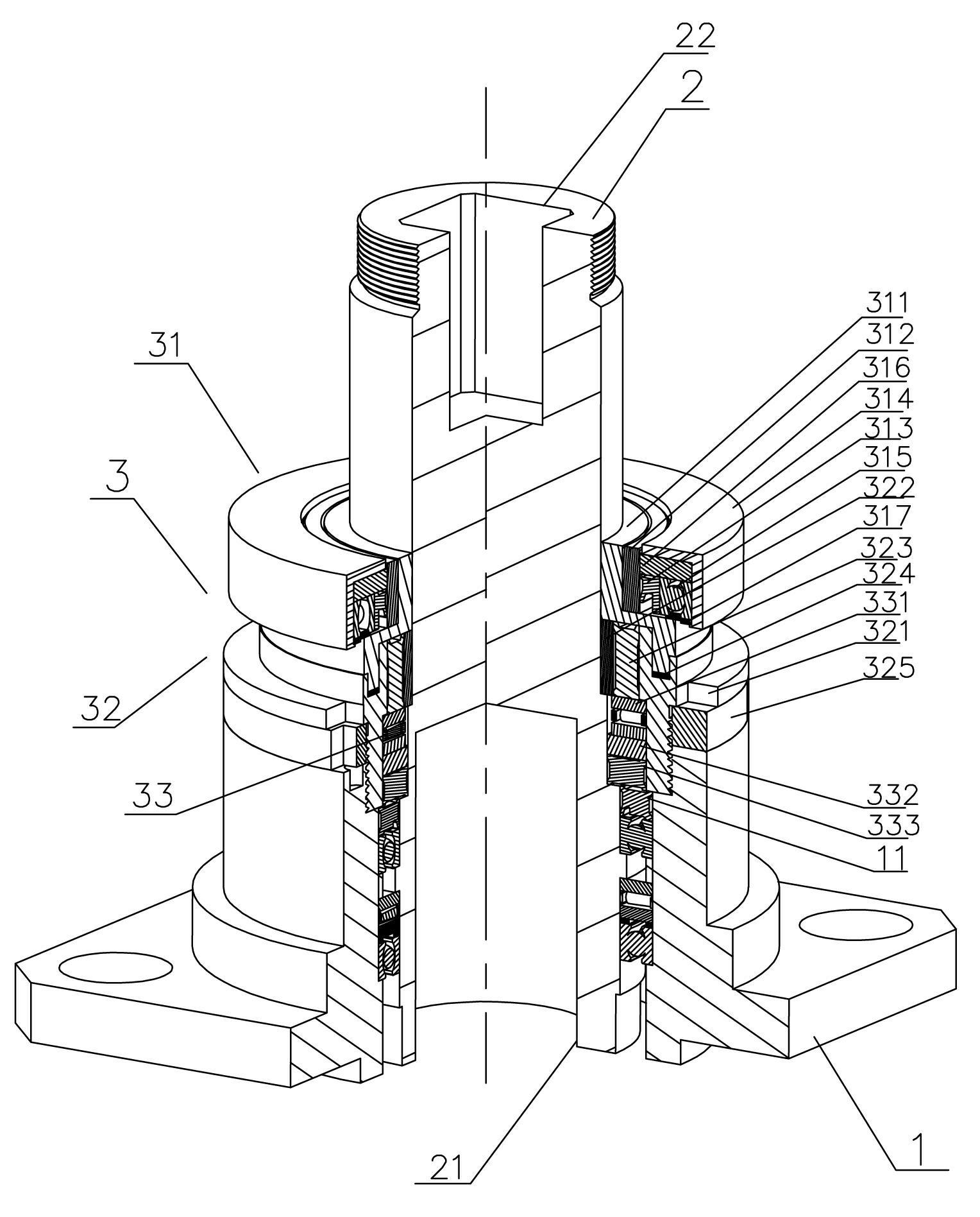
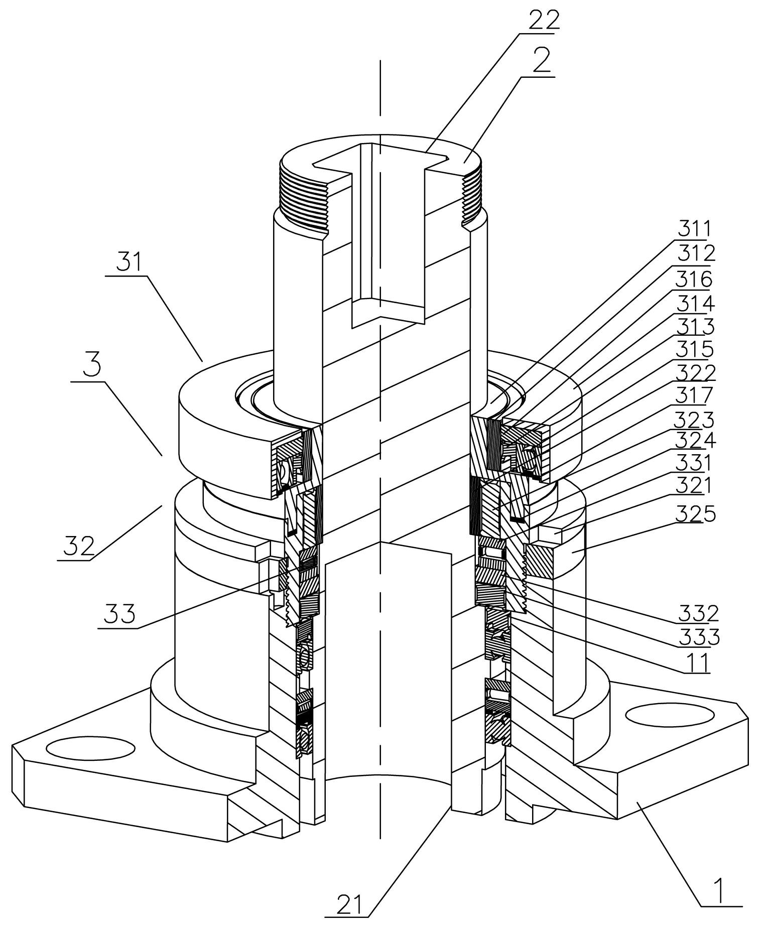
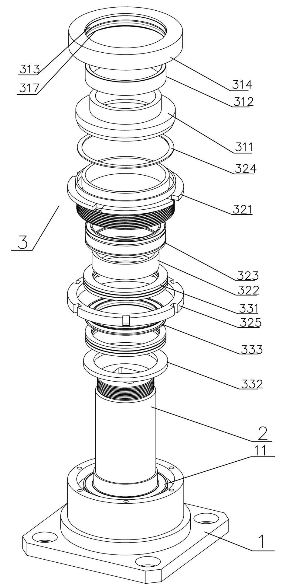
The invention discloses a pressure transmission sealing coupler. The coupler comprises a base in which an axial cavity is formed, wherein a rotating shaft which is provided with an input shaft interface and an output shaft interface passes through the axial cavity; the output shaft interface is positioned above the whole mechanism, and the input shaft interface is positioned below the whole mechanism; a bearing component and a base oil seal positioned above the bearing component are arranged between the rotating shaft and the base; and the base oil seal is provided with a waterproof pressure reducing sealing component which is compacted with the base oil seal, has an annular integral structure and is sleeved at the periphery of the rotating shaft and connected with the base. The waterproof pressure reducing sealing component is arranged, so that the bearing component in the coupler smoothly rotates and is prevented from being blocked, worn and burnt out even if the coupler works in an environment filled with particle impurities, and the service life of parts is prolonged; zero leakage is achieved, and the coupler has a good pressure reducing effect and a good axial movement prevention effect when working in a pressure transmission mode; and the coupler has a smart and compact structure and a wide application range, and can be applied to various shaft coupling occasions.
Description
Pressure type transmission seal coupling technical field The invention relates to a coupling, in particular to a pressure transmission coupling. Background technique In engineering production, the coupling is a common accessory that is widely used to connect the driving shaft and the driven shaft. It is generally provided with a driving shaft interface and a driven shaft interface, and then a bearing assembly and a sealing assembly are arranged between the two interfaces. However, ordinary couplings usually have a limited degree of sealing. During rotation, they are prone to jamming and water leakage due to the penetration of foreign impurities, resulting in severe wear and tear of bearings, oil seals and other accessories, and they have to be replaced. If the sealing effect is to be ensured, many components must be added oil seal, but it is often not possible due to the limitation of installation space; in addition, if the coupling adopts pressure transmission, it will p...
Claims
Login to View More Application Information
Patent Timeline
 IPC IPC(8): F16D1/02
Inventor任宇
Owner任宇