
Ventilation device

A technology for ventilation devices and fans, which is applied in pump devices, ventilation systems, space heating and ventilation, etc., to achieve the effects of easy promotion, pleasant flow rate, and obvious cooling effect.

Inactive Publication Date: 2013-04-10
曾小颖 +1
View PDF2 Cites 4 Cited by
  • Summary
  • Abstract
  • Description
  • Claims
  • Application Information

AI Technical Summary

Problems solved by technology

[0005] In order to overcome the defect that the existing ventilation device does not have the air conditioning function, the present invention aims to provide a suction ventilation device with a hidden impeller form, a spray device and an annular nozzle, which can be used to adjust the temperature and humidity of the air As well as the flow rate, it brings a comfortable cool wind to the surrounding environment similar to that blowing by the lake and the sea.

Method used


Image

  • Ventilation device
  • Ventilation device
  • Ventilation device

Examples


Embodiment 2

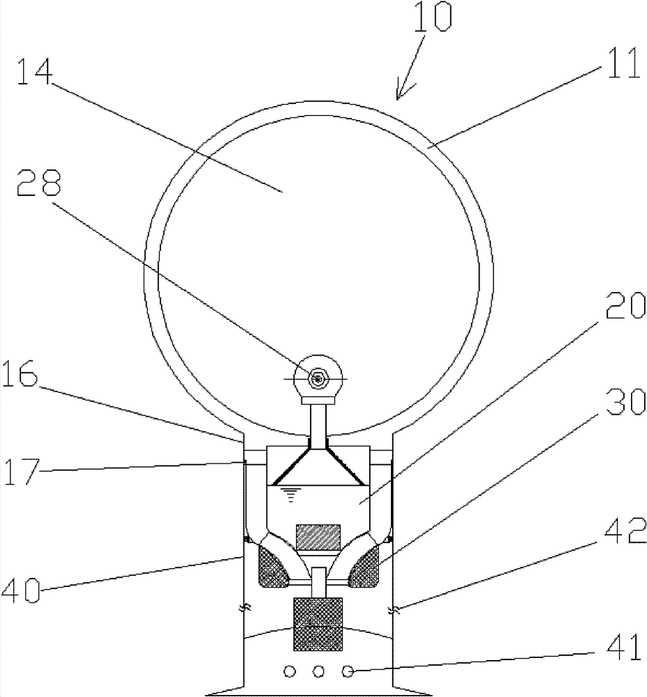
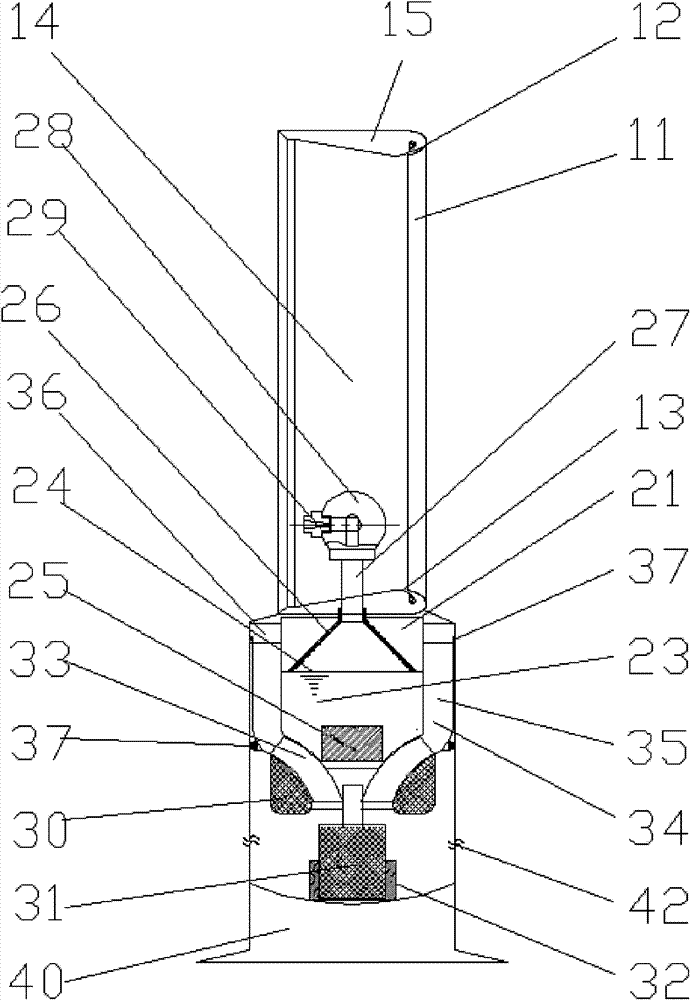
[0048] a ventilation device such as Figure 7 As shown, it includes a base 40 , a water vapor generator 20 located at the bottom of the base 40 and a high-speed fan 30 on the top of the base 40 . The air outlet of the high-speed fan 30 is provided with an annular injector 11 fixed on the base 40 ; The water vapor produced by the water vapor generator 20 is sent into the high-speed fan 30 together with the air entering the air inlet hole 42, and is sprayed out by the annular injector 11 to achieve the same thinning effect. This type of design facilitates the installation of multiple ultrasonic nebulizers 25, and is suitable for applications in particularly dry places.

[0049] Other structures and working principles of the ventilation device are the same as those in Embodiment 1, and will not be repeated here.


PUM


Abstract

The invention discloses a ventilation device, which aims to solve the problem that the conventional ventilation device does not have an air adjusting function. The device comprises a pedestal, a high-speed air blower and an annular ejector, wherein the high-speed air blower is arranged at the bottom of the pedestal; the annular ejector is arranged at an air outlet of the high-speed air blower and is fixed on the pedestal; and the air inlet or the air outlet of the high-speed air blower is provided with a vapor generator which is fixed on the pedestal for producing water vapor. In the ventilation device, the water vapor is produced through the vapor generator and is ejected through an atomization nozzle at a high speed to produce fog of smaller granularity, so that a hot air flow can more easily absorb the latent heat of vaporization, and the ventilation device has a humidification effect and a heat absorption and temperature reduction effect on a large amount of hot air sucked by the annular nozzle, and brings comfortable cool air similar to air on the shore of a lake or a sea to the surrounding environment. In the ventilation device, an external circulating device is not required to be mounted, so the cost is low; the space is not required to be closed, so that air convection is guaranteed; and the ventilation device is more energy-saving in the same temperature reduction range compared with a fan and an air conditioner, and can be used conveniently and safely.

Description

technical field [0001] The invention relates to a ventilation device, in particular to a ventilation device with adjustable air temperature, humidity and flow rate, which is especially suitable for use in dry and hot areas. Background technique [0002] Existing ventilation devices are usually equipped with obvious blades, or ventilation devices in the form of blades that have recently appeared (such as the devices introduced in Chinese invention patent application CN200910253241.6 and utility model patent CN200920292940.7). These ventilation devices have only made some improvements in the air flow rate and the uniformity of the flow. Although they all have the effect of ventilation and cooling, they do not have the function of air conditioning. Therefore, the effect of unilaterally relying on the cooling brought by increasing the air flow rate is often not obvious. In order to improve the cooling effect, only the speed of the ventilation device is increased, but at the same...

Claims


Application Information

Patent Timeline
Patent Type & Authority Patents(China)
IPC IPC(8): F24F7/007F24F6/14
CPCF04D25/08F04F5/16F04F5/463
Inventor 曾小颖曾振祥
Owner 曾小颖
Learn More