
Reaction torque test method and tester

A technology of reaction force and testing method, which is applied in the direction of instruments, measuring devices, torque measurement, etc., can solve the problems of complex principle and structure, high failure rate of instruments, high maintenance requirements, etc., and achieve simple structure, complex structure and high technical difficulty Effect

Inactive Publication Date: 2011-06-15
中国航天科技集团公司第九研究院七一〇七厂
View PDF3 Cites 8 Cited by
  • Summary
  • Abstract
  • Description
  • Claims
  • Application Information

AI Technical Summary

Problems solved by technology

[0006] Due to the complex principle and structure of the original instrument, the failure rate of the instrument is high during use, and the repair is difficult, which makes the daily maintenance requirement high, the maintenance time is long, and the cost is high

Method used

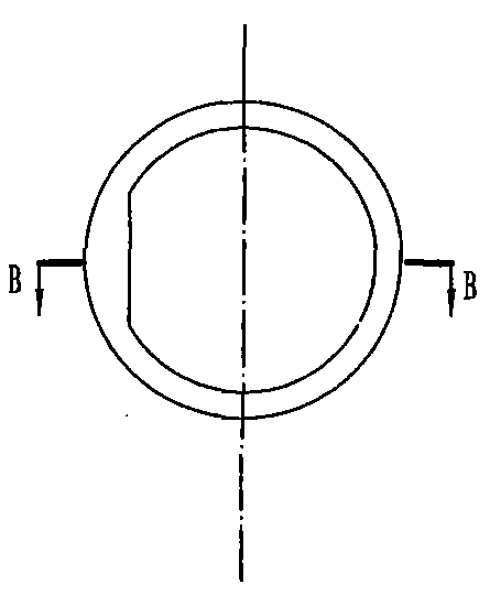
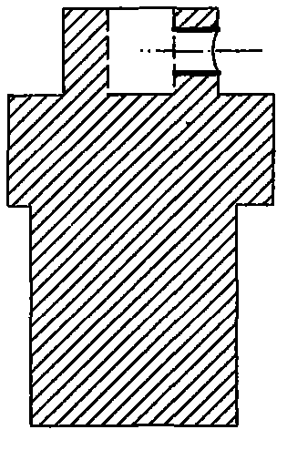

Image

  • Reaction torque test method and tester
  • Reaction torque test method and tester
  • Reaction torque test method and tester

Examples


Embodiment Construction

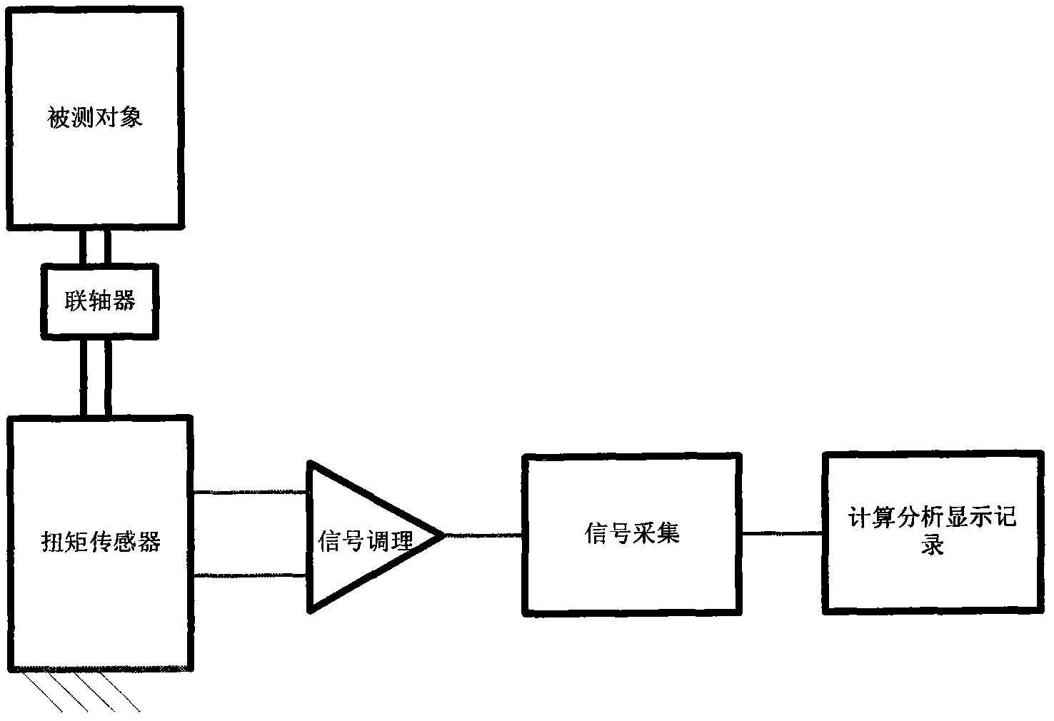
[0022] The reaction torque test method is to fix the stator shaft of the measured object through the coupling on the static torque sensor to obtain the electrical signal corresponding to the accurate small torque value of the measured object, and the electrical signal output by the sensor is processed by signal conditioning and data acquisition. Accurately obtain torque data; and use computer to process relevant data to obtain starting torque, load torque, friction torque and calculate inertia time and synchronization time.

[0023] The reaction torque tester for realizing the method has a static torque sensor, the coupling is fixed on the static torque sensor to obtain the accurate tiny torque value of the measured object, and the static torque sensor is connected with the signal conditioning and data acquisition system in turn Connect and access computer processing systems.

[0024] Through the analysis and research on the principle of motor parameter measurement, as long as...


PUM


Abstract

The invention relates to a method for testing reaction torque. The method comprises the following steps of: fixing a stator shaft of a tested object on a static torque sensor through a coupler to acquire an electrical signal corresponding to the accurate micro torque value of the tested object; carrying out signal conditioning and data acquisition to the electric signal output by the sensor to accurately acquire torque data; and processing related data by a computer to acquire start torque, load torque and friction torque and calculating inertia time and synchronizing time. The reaction torque tester for realizing the method is provided with the static torque sensor, the coupler is fixed on the static torque sensor to acquire the accurate micro torque value of the tested object, and the accurate micro torque sensor is sequentially connected with signal conditioning and data acquisition systems and accessed in a computer processing system. By analyzing and researching tested characteristics and the test principle, the static torque sensor is selected to acquire the accurate micro torque value and accurately acquire the torque data through signal conditioning and data acquisition.

Description

technical field [0001] The invention relates to the technical field of parameter testing instruments for precision micro-special motors, in particular to a testing instrument for parameters of micro-special motors with high rotational speed and low torque. Background technique [0002] Precision micro motors are widely used in inertial instruments such as electromechanical gyroscopes, gyro accelerometers, and rate gyroscopes. [0003] As the core component of the inertial instrument, the starting torque and friction torque of the motor have a great influence on the accuracy and stability of the inertial instrument. It is not easy to directly measure the starting torque and friction torque of the motor in the inertial instrument. [0004] Utilizing the principle that the action of force is mutual, the starting torque and friction torque of the motor can be measured by measuring the torque exerted by the rotor shaft on the motor stator shaft. As a design reference for inerti...

Claims


Application Information

Patent Timeline
Patent Type & Authority Applications(China)
IPC IPC(8): G01L3/00
Inventor 张博
Owner 中国航天科技集团公司第九研究院七一〇七厂
Learn More