
Device and method for testing power cable fault

A power cable and testing device technology, which is applied in the field of power cable fault testing devices, achieves the effects of light weight, simple operation and safe testing process

Inactive Publication Date: 2011-06-15
西安四方机电有限责任公司
View PDF4 Cites 15 Cited by
  • Summary
  • Abstract
  • Description
  • Claims
  • Application Information

AI Technical Summary

Problems solved by technology

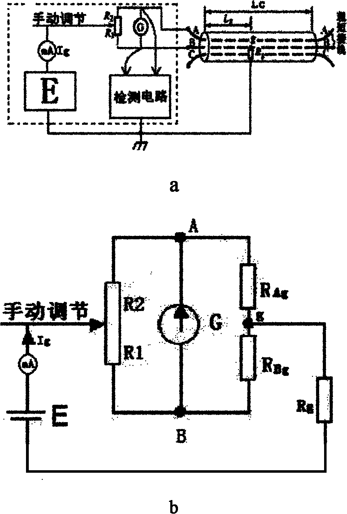
For most cable faults with resistance values ​​above hundreds of kilohms, use figure 1 The traditional power cable fault test device and test method shown in a are powerless

Method used


Image

  • Device and method for testing power cable fault
  • Device and method for testing power cable fault
  • Device and method for testing power cable fault

Examples


Embodiment 1

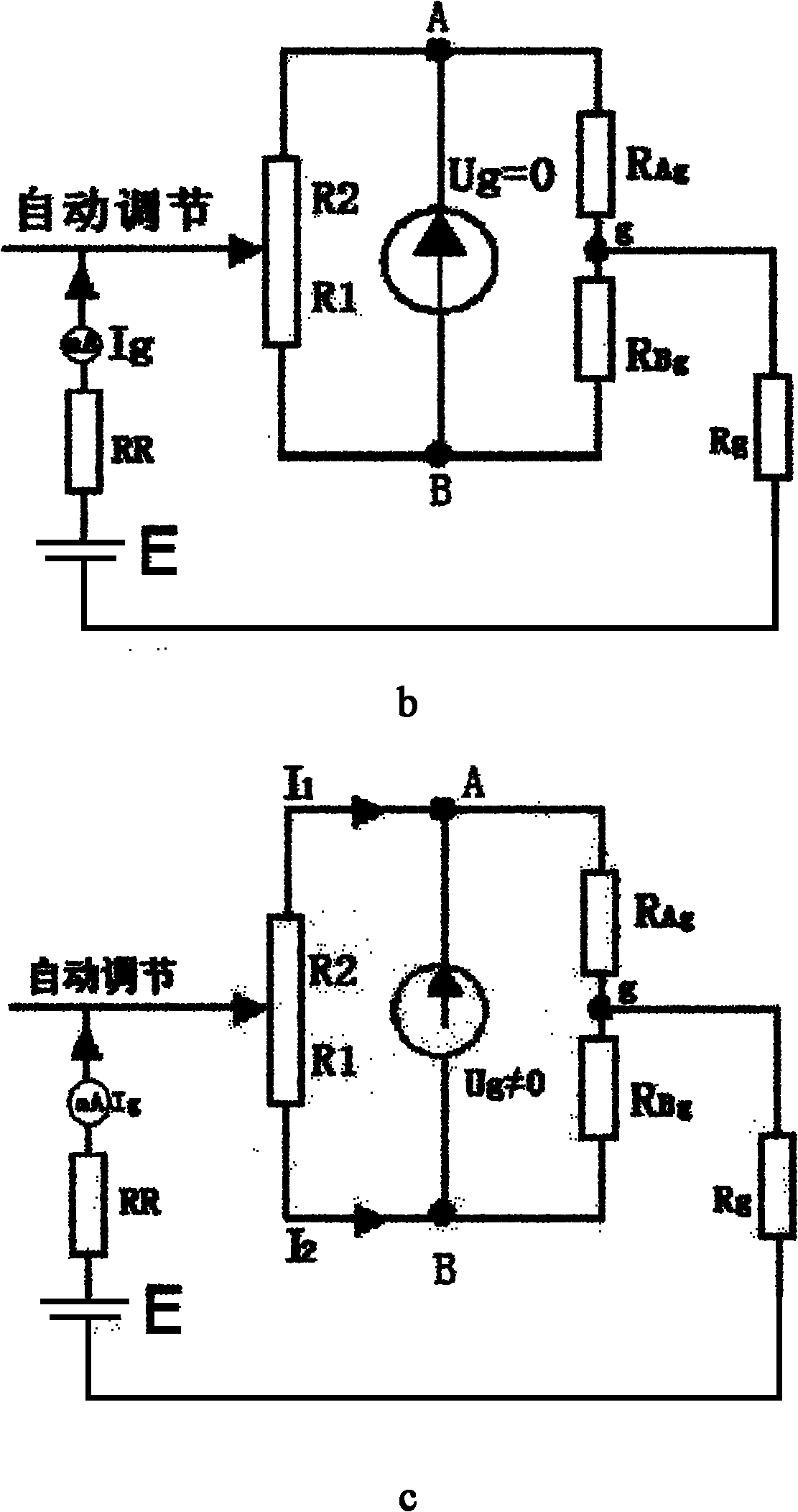
[0041] like figure 2 As shown in b, the bridge balance method. Include the following steps:

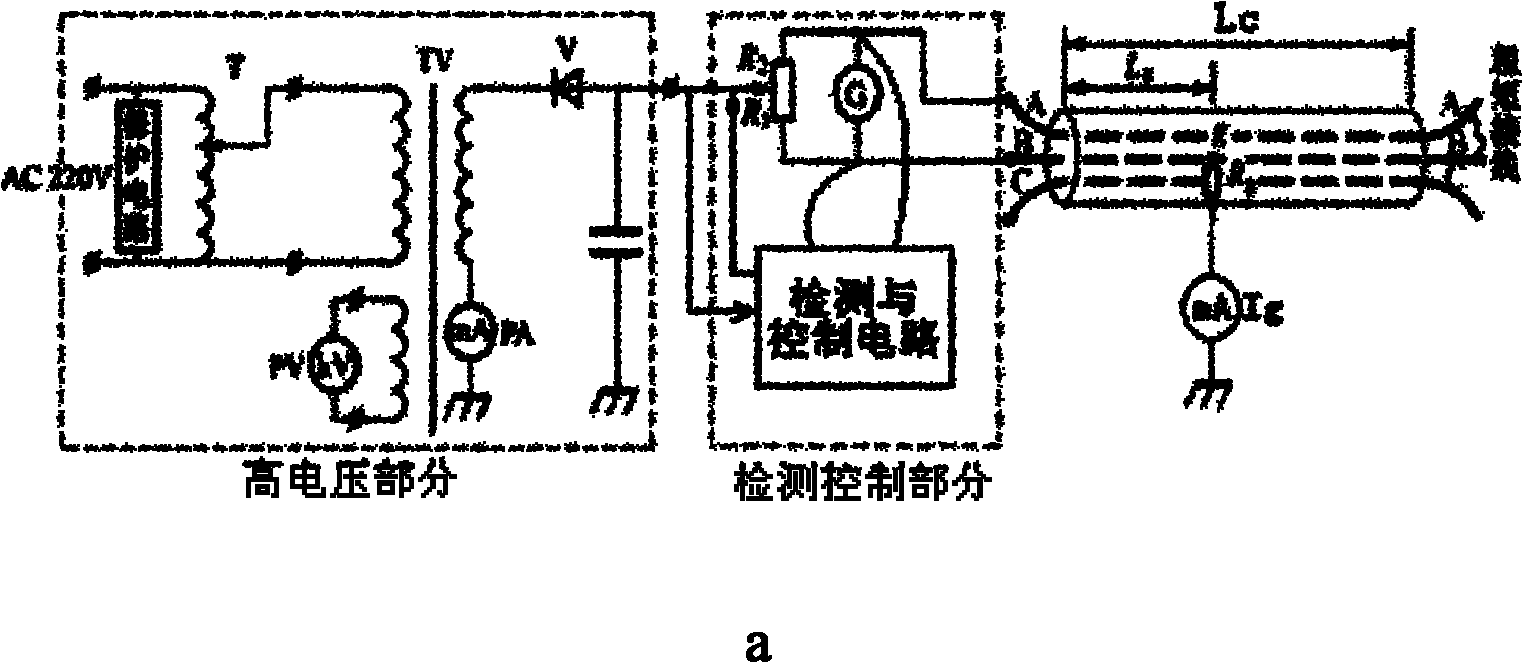
[0042] (1) Connect the two fixed ends of the potentiometer of the test device to any two phases A and B of the cable under test, one of which is a faulty phase, and connect the other ends of any two phases of the cable under test with thick and short wires to form a test A bridge circuit, the sliding end of the potentiometer is connected in series with a current sampling resistor RR to the output E of the high voltage part, and the fault test current acquisition end of the detection and control circuit is respectively connected to the two ends of the current sampling resistor RR; the detection and control circuit The control output end is connected to the sliding end of the potentiometer, and the detection signal end of the voltage across the test bridge of the detection and control circuit is separated from the high voltage part, and connected in parallel to the two fixed ends of t...

Embodiment 2

[0050] Bridge unbalance method. Include the following steps:

[0051] (1) Connect the two fixed ends of the potentiometer of the test device to any two phases of the tested cable, one of which is a faulty phase, and the other ends of any two phases of the tested cable are connected with thick and short wires to form a test bridge circuit , the sliding end of the potentiometer is connected in series with a current sampling resistor RR to the output E of the high voltage part, and the fault test current acquisition end of the detection and control circuit is respectively connected to the two ends of the current sampling resistor RR; the detection is connected to the control terminal of the control circuit To the sliding end of the potentiometer, the detection signal terminal of the voltage across the test bridge of the detection and control circuit is separated from the high voltage part, and connected in parallel to the two fixed ends of the potentiometer; then the potentiomete...


PUM


Abstract

The invention discloses a device and a method for testing a power cable fault. The device for testing the power cable fault comprises a high voltage part and a detection control part; the detection control part comprises a potentiometer and a detection and control circuit; two fixed ends of the potentiometer are connected with any two phases of a tested cable; one phase is a faulted phase; the sliding end of the potentiometer and the fault test current collection end of the detection and control circuit are connected with the output of the high voltage part; the control end of the detection and control circuit is connected to the sliding end of the potentiometer; and the detection signal end of the voltage at both ends of a test bridge of the detection and control circuit is isolated from the high voltage part and connected in parallel with the two fixed ends of the potentiometer. By the test method in which the high voltage part is isolated from the detection and control part, an operator can exert high voltage in a higher range to the tested faulted cable by regulating a voltage regulator on the low voltage side safely and reliably, so the tested fault resistance value is large, and the fault test range is enlarged greatly.

Description

technical field [0001] The invention relates to a testing device and method for a power cable fault, in particular to a device and a testing method for a power cable fault using the principle of a resistance bridge. Background technique [0002] The test methods for power cable faults are roughly divided into two categories: rough test method and fine test method. Among them, the rough measurement method is currently used in practice with two methods: the resistance bridge method and the pulse reflection method. As far as the resistance bridge method is concerned, it is mainly used to test a type of fault with a low single-phase insulation resistance value of the cable. Its principle is as follows: figure 1 as shown in a. [0003] The traditional test device is to combine the high voltage output E with the detection circuit part, adjust the relevant buttons on the instrument panel by operating, and finally calculate the distance from the cable fault point g to the test ter...

Claims


Application Information

Patent Timeline
IPC IPC(8): G01R31/08
Inventor 韩伯锋蒲灵娟路驹
Owner 西安四方机电有限责任公司
Learn More