Method for monitoring step profiler in measuring accuracy of chip groove depth

A groove depth and chip measurement technology, applied in measurement devices, semiconductor/solid-state device testing/measurement, instruments, etc., can solve the problems of not meeting the set depth requirements, time-consuming, inaccurate measurement data, etc. Guaranteed effect of accuracy

Active Publication Date: 2011-06-15
FOUNDER MICROELECTRONICS INT
View PDF0 Cites 17 Cited by
  • Summary
  • Abstract
  • Description
  • Claims
  • Application Information

AI Technical Summary

Problems solved by technology

[0005] (1) Since a large number of advanced slices are required for slice monitoring every time the groove is etched, and the current depth of the groove is measured by SEM, and then it is determined whether to adjust the dry etching groove according to the data obtained by SEM measurement The slot time, therefore, takes longer
[0006] (2) Some engraving equipment is in poor working condition, and when the etching rate fluctuates, the depth of the groove does not reach the set depth requirement. If the dry etching time is adjusted according to the fluctuating etching rate, it may cause The depth of the groove is inaccurate, which will lead to the yield of the product; in addition, if the SEM itself has the problem of low measurement accuracy, it may also lead to inaccurate measurement data obtained by measuring the current depth of the groove, resulting in The actual etched trench depth cannot meet the set depth requirement

Method used


Image

  • Method for monitoring step profiler in measuring accuracy of chip groove depth
  • Method for monitoring step profiler in measuring accuracy of chip groove depth
  • Method for monitoring step profiler in measuring accuracy of chip groove depth

Examples


Embodiment Construction

[0023] The embodiments of the present invention will be described in detail below in conjunction with the accompanying drawings of the specification.

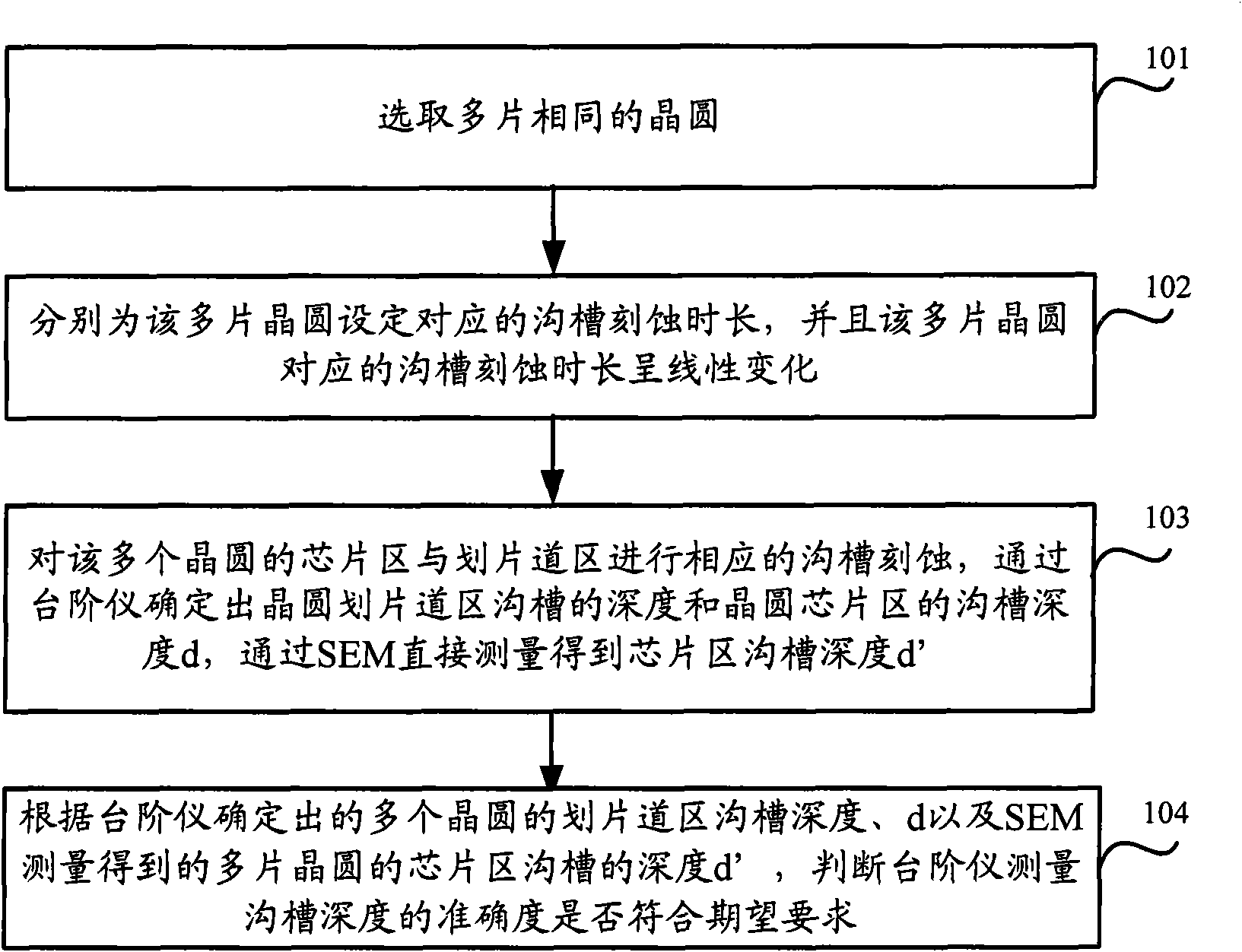
[0024] See Figure 1A , Is the method flow of the monitoring step meter measuring the accuracy of the chip groove depth in the embodiment of the present invention, and the flow includes the steps:

[0025] Step 101: Select multiple same wafers, including the same material and the same polarity.

[0026] Step 102: Set corresponding trench etching durations for the multiple wafers respectively, and the trench etching durations corresponding to the multiple wafers vary linearly.

[0027] Step 103: For each wafer, trench etching is performed in the chip area and scribing track area of ​​the wafer, and the trench etching time is the same as the set etching time corresponding to the wafer. A groove is formed in the scribing track area; and the depth of the groove in the scribing track area of ​​the wafer is measured by a step meter, and the ...


PUM


Abstract

The invention discloses a method for monitoring a step profiler in measuring the accuracy of chip groove depth, which reduces the delay on monitoring of the chip groove depth, improves the accuracy on monitoring of the groove depth and achieves the purpose of monitoring the step profiler in measuring the accuracy of the chip groove depth. The method comprises the following steps of: selecting a plurality of wafers, and determining the depth of a groove in a wafer chip area through measuring the depth of a groove in a wafer scribing channel area and the thickness of a hard mask layer by the step profiler in allusion to each wafer; and determining whether the accuracy of the groove depth measured by the step profiler reaches the requirements on the accuracy through analyzing the depth value of the groove in the chip area of the plurality of the wafers. By adopting the technical scheme, the time delay on monitoring of the chip depth can be shortened, the accuracy on controlling of the chip groove depth is improved, and the purpose of monitoring the step profiler in measuring the accuracy of the groove depth is realized.

Description

Technical field [0001] The invention relates to the technical field of semiconductor device layout design, and in particular to a method for measuring the accuracy of chip groove depth by a monitoring step meter. Background technique [0002] Source-drain breakdown voltage Bvdss and source-drain on-resistance Rdson are key parameters for low-voltage trench DMOS (DMOS) devices. These two parameters are more sensitive to each other. In general, the expected value of Bvdss is 20V~100V , The expected value of Rdson is less than ten milliohms. Because the values ​​of Bvdss and Rdson are related to the groove depth, different groove depths may determine Bvdss and Rdson with different values. Therefore, in the dry groove process In the process, it is particularly important to accurately control the depth of the trench. [0003] At present, the conventionally designed DMOS (Double-diffused Metal Oxide Semiconductor) trench lithography layer layout only needs to have trench patterns in the...

Claims


Application Information

Patent Timeline
Patent Type & Authority Applications(China)
IPC IPC(8): H01L21/00H01L21/66G01B11/22
Inventor 陈勇方绍明张立荣王新强曾永祥
Owner FOUNDER MICROELECTRONICS INT
Why Eureka
Try Eureka