Supercharge Your Innovation With Domain-Expert AI Agents!

Liquid test strip

A fluid detection and test piece technology, applied in measuring devices, instruments, scientific instruments, etc., can solve the problems of flow channel blockage, measurement error, test failure, etc., to avoid blocking flow channels, accurate quantitative analysis results, and avoid liquid residues Effect

Inactive Publication Date: 2013-12-18
ACTHERM INC
View PDF8 Cites 0 Cited by
  • Summary
  • Abstract
  • Description
  • Claims
  • Application Information

AI Technical Summary

Problems solved by technology

However, regardless of any of the above methods, after the fluid to be tested is injected into the flow channel, air bubbles of different sizes are often generated or involved to block the flow channel, causing errors in actual measurement, and even lead to test failure. Micro-actuator or valve) increases the difficulty of the overall design and the cost of test pieces
[0004] Finally, the test pieces of the known technology often use die casting, injection molding or imprinting (imprint) to make flow channel or micro channel structure on the substrate, so polyethylene (PE), poly Higher-priced plastic polymers such as vinyl chloride (PVC) or polypropylene (PP) are used as materials and the mold wears out quickly, resulting in an increase in the overall cost of the test piece

Method used


Image

  • Liquid test strip
  • Liquid test strip
  • Liquid test strip

Examples


Embodiment Construction

[0031] Since the present invention discloses a test piece for fluid detection, the physical and chemical principles and solution coating technology used in it are already understood by those with ordinary knowledge in the relevant technical field, so the following description will not be fully described. At the same time, the drawings compared below are schematic representations related to the features of the present invention, and are not and need not be completely drawn according to the actual situation, so they will be described here first.

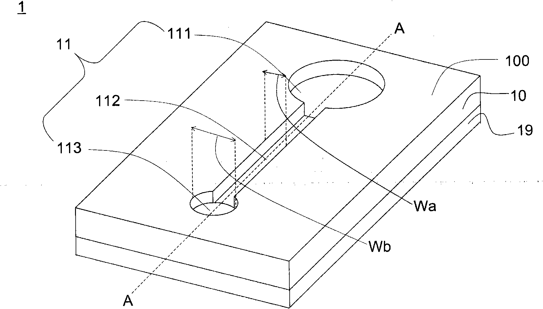
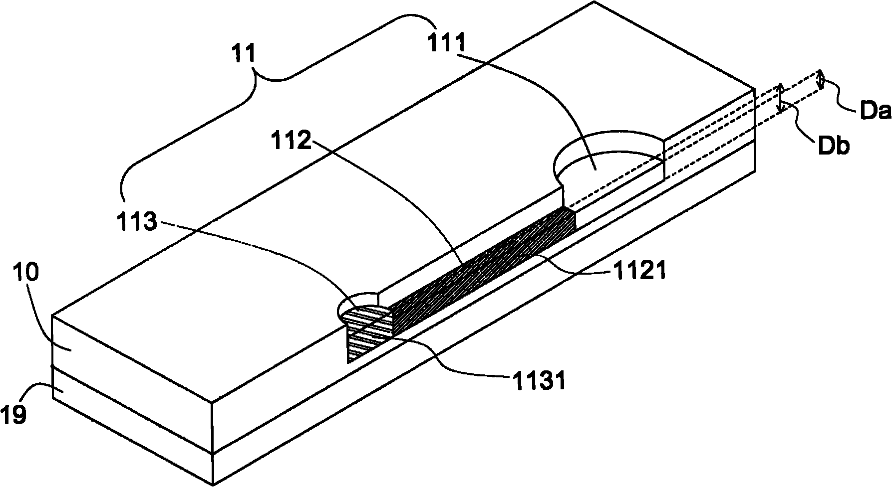
[0032] Such as Figure 1A Shown is a schematic diagram of the first embodiment of the present invention. The fluid detection test strip 1 includes a substrate 10 and a support 19 . The substrate 10 is recessed from the upper surface 100 to define a flow channel 11 , and the flow channel 11 includes a first fluid area 111 , a second fluid area 112 and a third fluid area 113 connected in sequence. The first fluid area 111 is used for th...


PUM


Abstract

This invention discloses an analytical strip comprising a substrate. The substrate has a channel provided concavely on the upper surface thereof. The channel comprises a first area for receiving a fluid sample, a second area for delivering the fluid sample, and a third area where the fluid sample reacts. These three areas are connected sequentially. Nitrocellulose layers are formed at the bottoms of both the second area and the third area. Each of the nitrocellulose layers comprises a hollow-matrix conformation. In addition, the nitrocellulose layer of the second area has an average thickness that is not greater than that of the nitrocellulose layer of the third area. The strip also comprises a reaction material formed in the hollow-matrix conformation of each of the nitrocellulose layers.

Description

technical field [0001] The invention relates to a detection test piece, in particular to a fluid detection test piece used in biochemical detection and immunological detection. Background technique [0002] In the known technology of biochemical detection and immunoassay using fluid detection test strips, fluid detection test strips are designed with flow channel or micro-channel structure and surface hydrophilic and hydrophobic treatment on the substrate or substrate, and because the flow channel is not surrounded by water-absorbing materials , and the fluid to be tested mostly contains high-viscosity components such as proteins or sugars, so when the fluid to be tested flows through, it will remain on the flow channel, making the fluid to be tested unable to fully react. In this way, not only The waste of fluid to be tested is more likely to cause errors in the final test results. [0003] In addition, the fluid detection test piece of the known technology can be designed...

Claims


Application Information

Patent Timeline
Patent Type & Authority Patents(China)
IPC IPC(8): G01N33/543G01N33/558
CPCG01N33/54386G01N33/558G01N33/54388G01N33/538
Inventor 谢治纬谢文彬吴怡荏
Owner ACTHERM INC
Features
  • R&D
  • Intellectual Property
  • Life Sciences
  • Materials
  • Tech Scout
  • Unparalleled Data Quality
  • Higher Quality Content
  • 60% Fewer Hallucinations
Learn More