Power electronics device

A technology of power electronics and power electronic units, applied in the direction of circuits, electrical components, electric solid devices, etc., to achieve good heat dissipation, compact structure, saving materials and assembly costs

Inactive Publication Date: 2011-06-15
ROBERT BOSCH GMBH
View PDF1 Cites 0 Cited by
  • Summary
  • Abstract
  • Description
  • Claims
  • Application Information

AI Technical Summary

Problems solved by technology

[0003] In principle, in power electronics of this type there is on the one hand the problem that due to the high heat release during operation an effective heat removal must be ensured

Method used


Image

  • Power electronics device
  • Power electronics device
  • Power electronics device

Examples


Embodiment Construction

[0028] In these figures, the same components are provided with the same reference numerals.

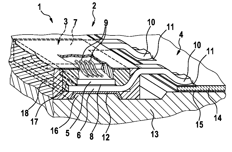
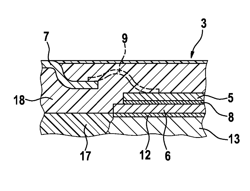
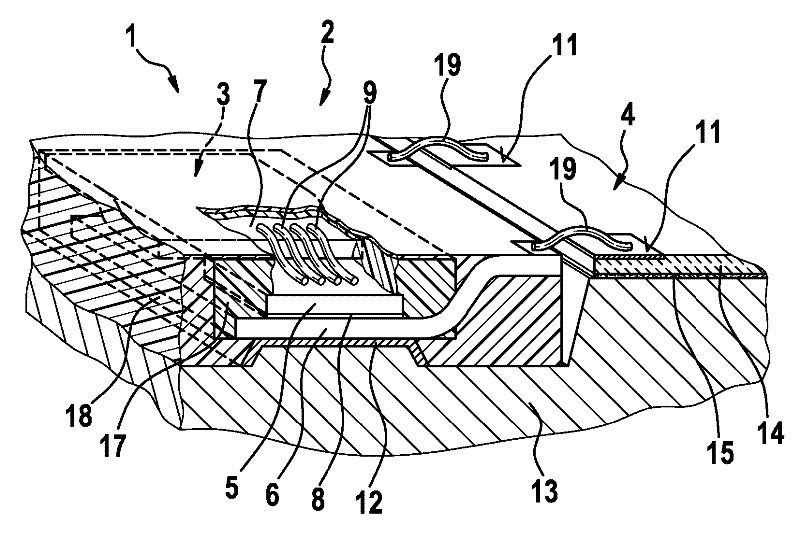
[0029] figure 1 The power electronics 1 shown in is an integrated power unit (IPU) with electronic components 2 comprising a power electronics unit 3 and a signal electronics unit 4 . The power electronics unit 3 has a power semiconductor element 5 , for example a chip, which is electrically connected to the lower copper layer 6 and the upper copper layer 7 . The connection between the semiconductor element 5 and the lower copper layer 6 takes place via an electrically conductive connection layer 8 , which is designed, for example, as a solder layer or as an electrically conductive sintered layer. The electrical connection between the top contact, ie, the semiconductor element 5 and the copper layer 6 lying above it, takes place via a plurality of bonding wire connections 9 .

[0030] The electrical connection between the power electronics unit 3 and the signal electronics unit 4 ta...


PUM


Abstract

The invention relates to a power electronics device comprising an electronic component arranged on a base plate. The electronic component has a power electronics unit and a signal electronics unit. The electronic component is at least partially encapsulated with a plastic.

Description

technical field [0001] The invention relates to a power electronics device having electronic components arranged on a substrate. technical background [0002] DE 102 60 851 A1 describes a power electronics system having power components arranged on a heat sink, wherein the power components are electrically coupled to the circuit carrier via bonding wire connections. The circuit carrier and the heat sink of the power components are held on a common substrate. For example power semiconductors such as power transistors, power diodes or ASICs are considered as power devices. [0003] In principle, in power electronics of this type there is on the one hand the problem that, due to the high heat dissipation during operation, effective heat removal has to be ensured. On the other hand, the components must have high mechanical stability. Contents of the invention [0004] The object of the present invention is to provide, with simple measures, a compact electronic device which ...

Claims


Application Information

Patent Timeline
Patent Type & Authority Applications(China)
IPC IPC(8): H01L23/31H01L23/34H01L23/433H01L23/498
CPCH01L2924/19107H01L25/16H01L2224/49111H01L23/3135H01L2924/1433H01L2224/48472H01L2224/48091H01L23/433H01L2224/73265H01L2224/48247H01L2924/00014H01L2924/00
Inventor J.杜尔S.凯尔J.基尔彻G.福格勒A.迪尔曼
Owner ROBERT BOSCH GMBH
Why Eureka
Try Eureka