
Multifunctional hydraulic pile hammer

A multi-functional pile driver technology, applied in the direction of mechanical equipment, reciprocating drilling rigs, rotary drilling rigs, etc., can solve the problems of loose soil and rock structure around the pile body, slow pile driving speed, and poor stability of the pile body, so as to save time and Cost, low cost, smooth operation effect

Inactive Publication Date: 2011-06-22
陈才荣
View PDF6 Cites 5 Cited by
  • Summary
  • Abstract
  • Description
  • Claims
  • Application Information

AI Technical Summary

Problems solved by technology

[0002] At present, there are two kinds of pile driving machines used on construction sites: a kind of rotary pile driver (see figure 1 Parts with the following labels), the structure of this pile driver is to use the drill pipe suspension frame 22 pulled up by the winch 14 to hold the drill pipe 5, and the drill pipe clamp 3 clamps the drill pipe 5, and the motor drives the drill pipe clamp through the transmission device 3 and the drill pipe 5 can be rotated to perform pile driving. When this pile driver drives piles on the loose soil layer, the pile driving speed is relatively fast, and the soil and rock structure around the pile body is stable, but when it encounters a rock layer, the pile driving speed is very slow. The piling depth is about 10cm; the other is an impact hammer piling machine (see figure 2 There are the parts with the following labels), the structure of this pile driver is to use the hoist 14 to pull up the impact hammer 23 and then suddenly loosen it, and use the weight of the impact hammer 23 and the gravitational potential energy formed by the lifting height to directly below the impact hammer 23. The borehole 80 is impacted and crushed to form a borehole. When piling the rock layer, the piling depth per hour is about 100cm, which is about 10 times higher than the piling speed of the rotary piling machine, but its disadvantages are; The surrounding soil and rock structure is loose due to the impact, which makes the stability of the pile body poor; in view of this situation, the usual method used on the construction site is to use a rotary pile driver to drive piles. When encountering a rock layer: one is to use a rotary pile driver. The shortcoming of rotary piling is that the piling time is slow; the second is to withdraw the rotary piling machine, and then transport an impact hammer piling machine to perform impact piling on the rock layer. After the rock layer is penetrated, the original The rotary piling machine is used for rotary piling, because the piling depth of general high-rise buildings is mostly around 30-50m, and any stratum structure may encounter

Method used


Image

  • Multifunctional hydraulic pile hammer
  • Multifunctional hydraulic pile hammer
  • Multifunctional hydraulic pile hammer

Examples


Embodiment Construction

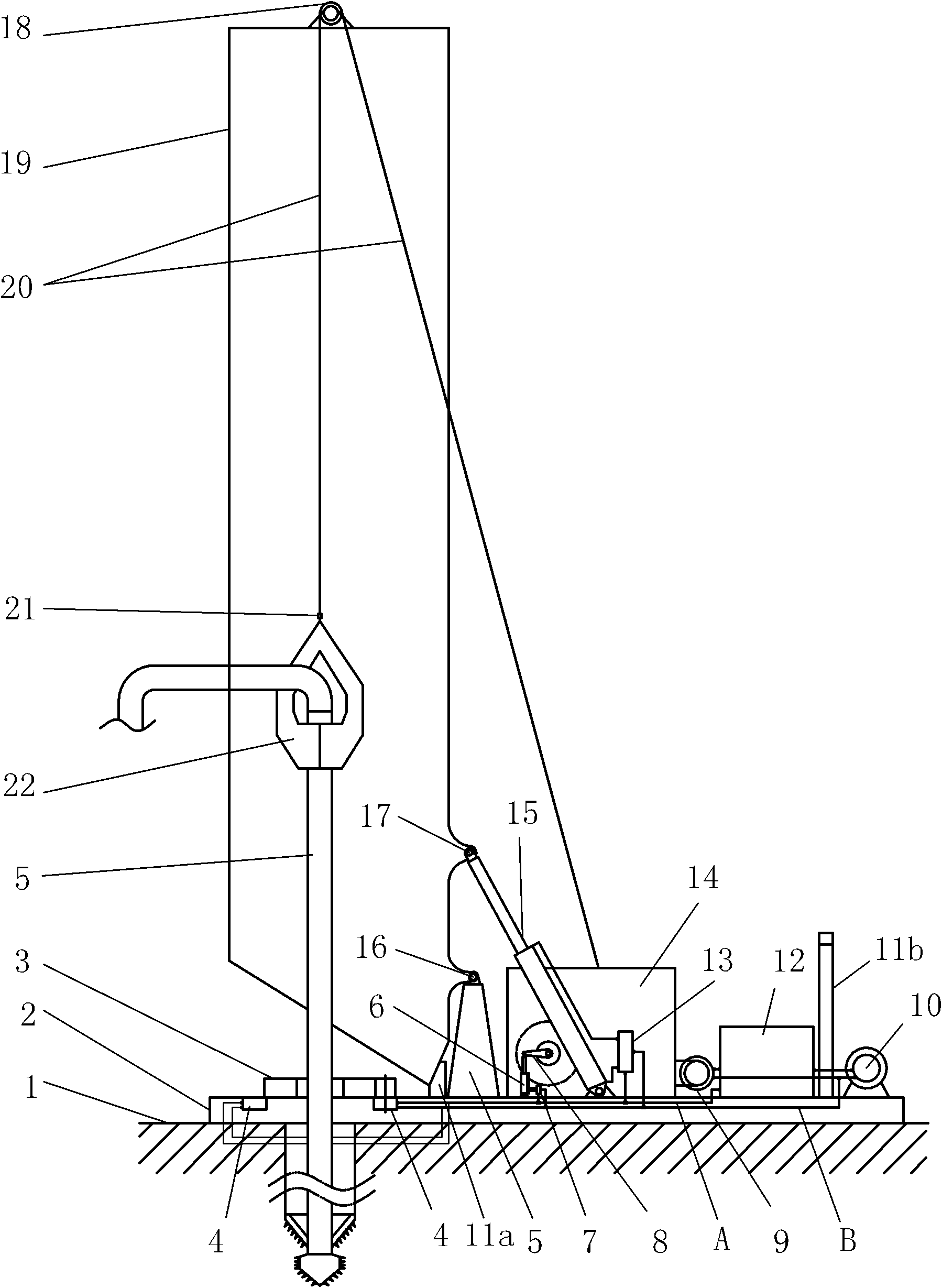
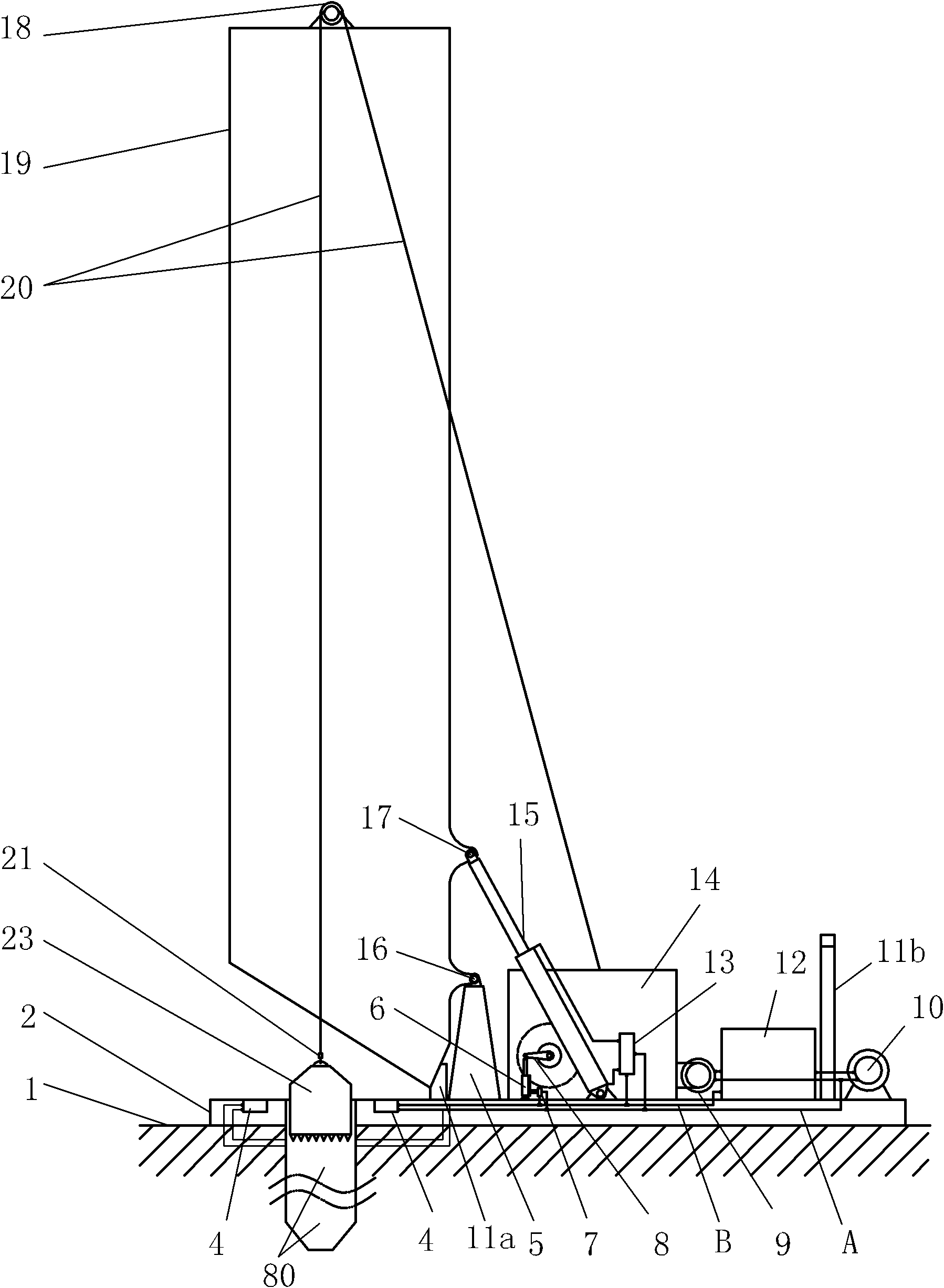
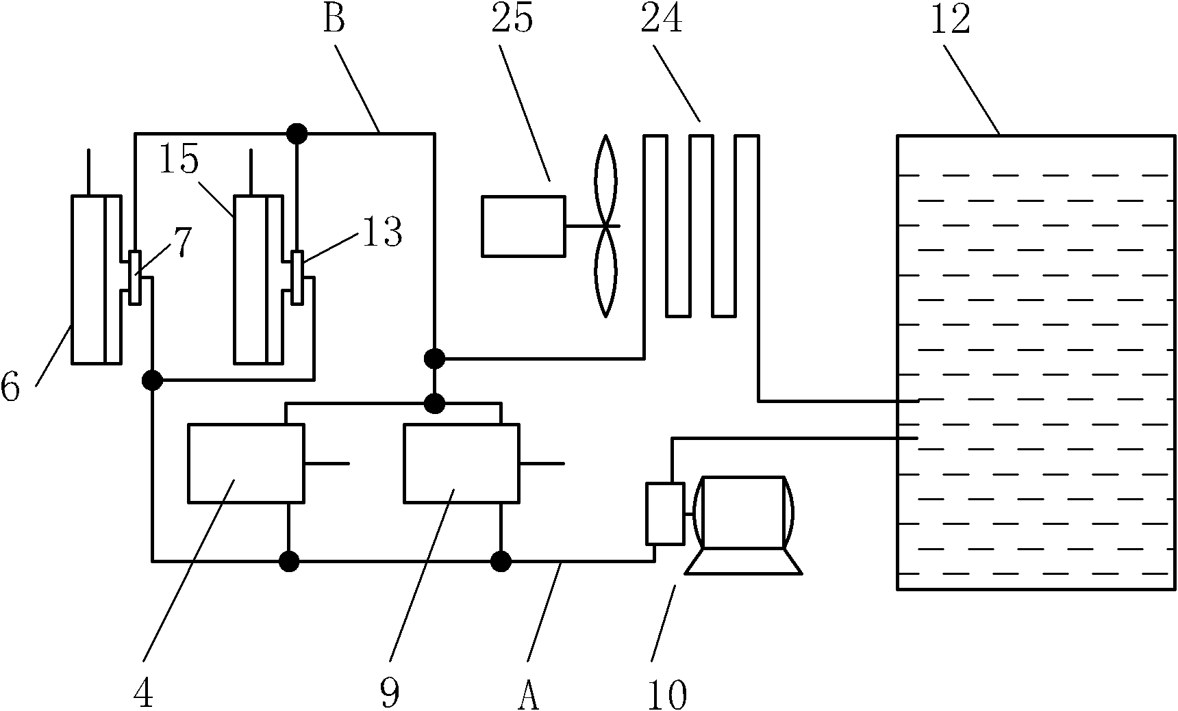
[0019] Below in conjunction with accompanying drawing, the present invention will be further described with specific embodiment, see Figure 1-4 :

[0020] The multifunctional hydraulic pile driver includes a base 2, a hoist 14 and a gantry 19. A drill pipe clamp 3 is arranged at one end of the base 2, and the drill pipe clamp 3 is driven to rotate by the first hydraulic motor 4 of the hydraulic system. The hoist 14 The second hydraulic motor 9 of the hydraulic system drives it to rotate, and one end of the gantry 19 is hinged on the base stand 5 next to the drill pipe fixture through the rotating shaft 16, and is driven by the first hydraulic cylinder 15 to stand up or fall down. , the base 2 is provided with a stop block 11a for erecting the gantry 19 and a support 11b for falling down, the top of the gantry 19 is provided with a pulley 18, and the extension end 21 of the steel cable 20 driven by the hoist 14 passes through the pulley 18 and the drill. The rod suspension fr...


PUM


Abstract

The invention belongs to the technical field of pile hammer for buildings, and relates to a multifunctional hydraulic pile hammer which comprises a pedestal, a windlass, a portal frame and a hydraulic system; a drill rod clamp is arranged at one end of the pedestal; the drill rod clamp and the windlass are respectively driven by a first hydraulic motor and a second hydraulic motor to rotate; the portal frame is hinged on a vertical frame on one side of the pedestal; a first hydraulic cylinder drives the portal frame to be erected or put upside down; the top of the portal frame is provided with a pulley; a steel cable driven by the windlass passes through the pulley and is respectively connected with a drill rod hanging frame and an impact hammer; and the action of the hydraulic system is controlled by a controller. The invention has the following beneficial effects: multiple performances are integrated on one machine; the multifunctional hydraulic pile hammer has good performance and low cost, and is suitable for quickly piling high-rise buildings, bridges and railways in various building fields.

Description

technical field [0001] The invention belongs to the technical field of construction pile drivers, in particular to a multifunctional hydraulic pile driver. Background technique [0002] At present, there are two kinds of pile driving machines used on construction sites: a kind of rotary pile driver (see figure 1 Parts with the following labels), the structure of this pile driver is to use the drill pipe suspension frame 22 pulled up by the winch 14 to hold the drill pipe 5, and the drill pipe clamp 3 clamps the drill pipe 5, and the motor drives the drill pipe clamp through the transmission device 3 and the drill pipe 5 can be rotated to perform pile driving. When this pile driver drives piles on the loose soil layer, the pile driving speed is relatively fast, and the soil and rock structure around the pile body is stable, but when it encounters a rock layer, the pile driving speed is very slow. The piling depth is about 10cm; the other is an impact hammer piling machine (s...

Claims


Application Information

Patent Timeline
Patent Type & Authority Applications(China)
IPC IPC(8): E21B1/00E21B1/02E21B3/00E21B3/02E21B15/00F15B21/04
Inventor 陈才荣
Owner 陈才荣
Learn More