Vacuum energy all-weather S-shaped airfoil rotational flow power generating system

A power generation system, all-weather technology, applied in wind power generation, renewable energy power generation, machines/engines, etc., can solve problems such as difficult installation and application, difficult installation and use, ecological impact, etc., to improve efficiency, low cost, and easy processing. Effect

Inactive Publication Date: 2011-06-22
上海兆锟光电科技有限公司 +2
View PDF0 Cites 0 Cited by
  • Summary
  • Abstract
  • Description
  • Claims
  • Application Information

AI Technical Summary

Problems solved by technology

[0003] 1. Intermittent power generation, only when there is wind can generate electricity, and no wind or small wind can not generate electricity, so there is a bottleneck in parallel connection with the power grid
[0004] 2. It covers a large area and has an impact on the ecology. It is a centralized power supply, with long transmission lines, high cost, and prone to failure.
[0005] 3. It is not easy to install and use in the city, and it is not easy to install and use in every household

Method used


Image

  • Vacuum energy all-weather S-shaped airfoil rotational flow power generating system
  • Vacuum energy all-weather S-shaped airfoil rotational flow power generating system
  • Vacuum energy all-weather S-shaped airfoil rotational flow power generating system

Examples


Embodiment 1

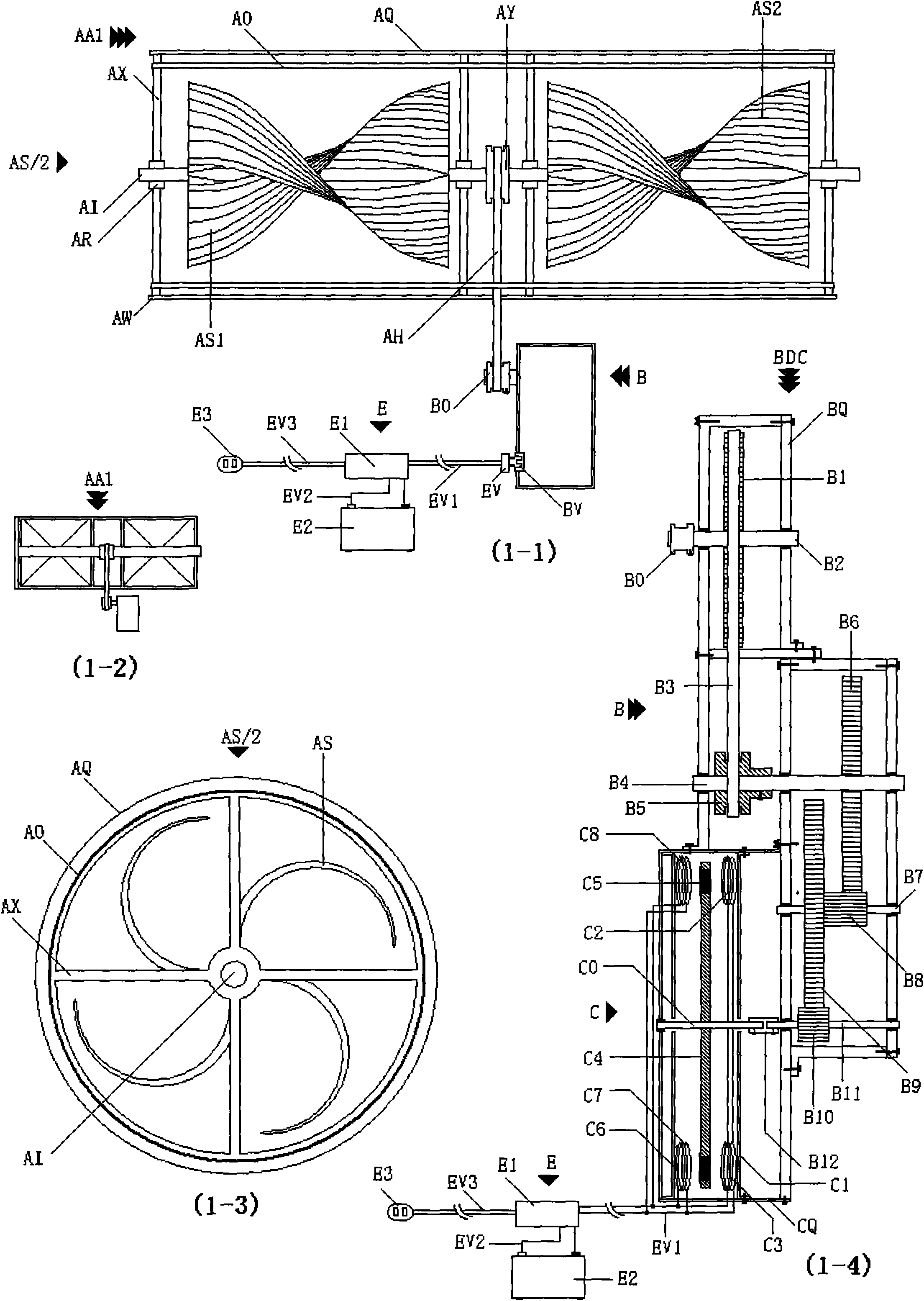
[0084] exist figure 1 , 2 Middle: S-type impeller airflow generator (AA1), referred to as: S-type generator (AA1); S-type impeller device (AS / 2), referred to as: S-type impeller (AS / 2); magnetic rotary power storage device (BCE ), referred to as: magnetic generator / storage device (BCE); fixed bracket (AX), frame (AQ), poly flow cover (A0), connecting ring (AW), S-shaped impeller (AS), S-shaped impeller (AS1) , S-shaped impeller (AS2), 1st stage transmission shaft (AI), bearing (AR), 1st stage transmission wheel (AY), 1st stage transmission belt (AH), speed increaser (B), magnetic generator / storage device (BCE ), 3rd stage transmission wheel (B1), 2nd stage transmission shaft (B2), 2nd stage transmission wheel (B0), 2nd stage transmission belt (B3), 3rd stage transmission shaft (B4), 4th stage transmission wheel (B5), 5 Stage transmission gear (B6), 4 stage transmission shaft (B7), 6 stage transmission gear (B8), 7 stage transmission gear (B9), 8 stage transmission gear (B10)...

Embodiment 2

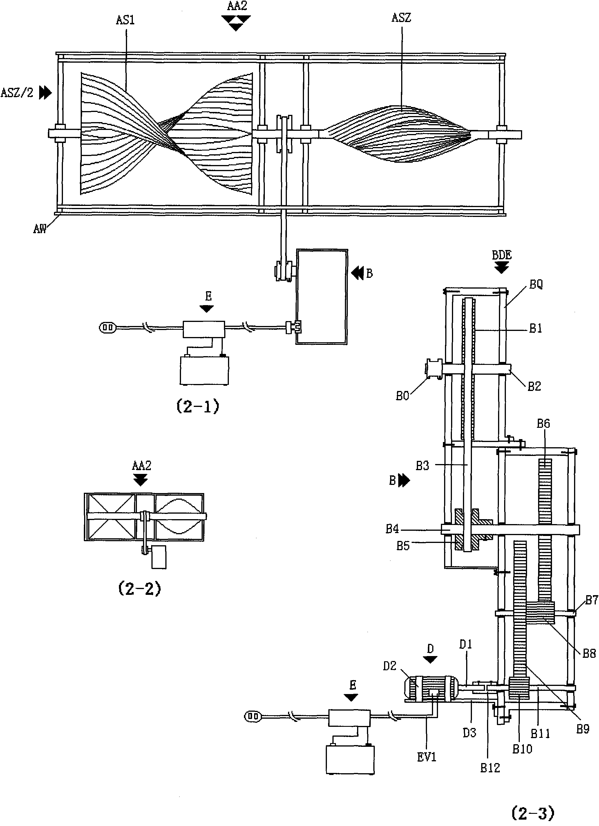
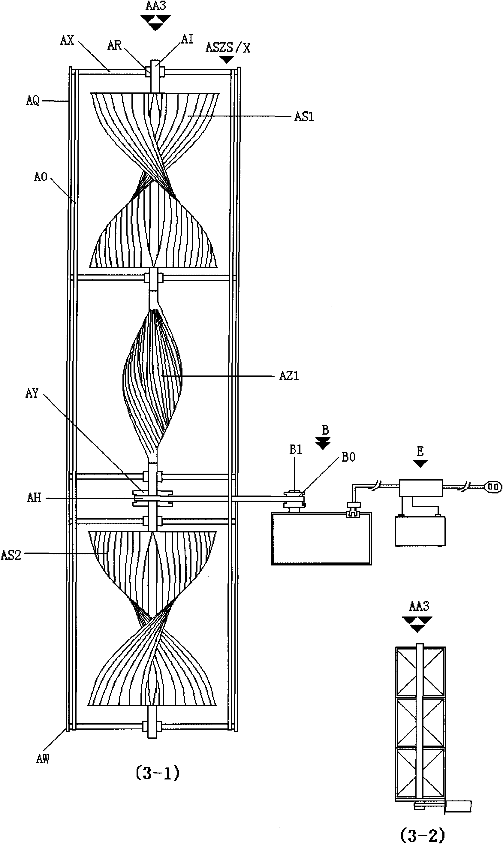
[0087] exist image 3 , 4 Middle: SZS generator (AA3), SSS generator (AA4), SZS impeller airflow device (ASZS / X), (AZ1) S-shaped impeller, S-shaped impeller (AS1), S-shaped impeller (AS2), S-shaped impeller (AZ1), connecting ring (AW).

[0088] In the figure: the overall structure is the same as figure 1 and 2 As shown in , the difference is; the SZS generator (AA3) is spirally connected to the S-shaped impeller (AS1) and the S-shaped impeller (AS2) at both ends of the first-stage transmission shaft (AI); the middle connection The Z-shaped impeller (ASZ) is 90 degrees with the S-shaped impeller (AS1) and the S-shaped impeller (AS2);

[0089] The SSS generator (AA4) is spirally connected with the S-shaped impeller (AS1) and the S-shaped impeller (AS2) at the two ends and the middle of the first-stage transmission shaft (AI).

Embodiment 3

[0091] exist Figure 5 Middle: wing S impeller type airflow generator (AA5), abbreviation: wing S impeller generator (AA5); wing blade (QQ), air intake channel (AG), connecting pipe seat (AK), air exhaust Outlet (AU), Upward Swirl (N6), Swirl (N6-1), Swirl S Blade Rotation (N6-2), Swirl S Blade Rotation (N6-3), Exhaust Airflow (N6-4).

[0092] In the figure: the S-type generator (AA5) includes a fixed support (AX) connected in a circular outer frame (AQ), and a heat-preserving air-gathering cover (A0) is connected outside the fixed support (AX); The center of the fixed bracket (AX) is connected to the bearing (AR), and the first-stage transmission shaft (AI) is connected to the bearing (AR), and the two ends of the first-stage transmission shaft (AI) are spirally connected to the S-shaped impeller (AS1 ) and S-shaped impeller (AS2); at the same time, the wing frame (QX) is connected in the bearing (AR), and the wing blade (QQ) with adjustable angle is connected to the outer r...


PUM


Abstract

The invention relates to a vacuum energy all-weather S-shaped airfoil rotational flow power generating system which consists of a vacuum energy heat souce collecting pump, a vacuum energy heat source storing tank, a vacuum energy generating pump, a rotational flow vertical drum, an air flow generator, a power generating device of the generator, a magnetic rotational power generating and storing device and a power supply. The power generating system provided by the invention is developed according to the principle of 'vacuum energy' and 'lift force of a airfoil' as well as the lifting force of a spiral flying disk; all-weather power generation of various power generators is driven by high-speed rotation of airfoil lifting force which is connected to S-shaped spiral rotational blades and is pushed by high-speed rotational air flow generated by the temperature difference of the 'vacuum energy'. The vacuum energy all-weather S-shaped airfoil ratational flow power generating system has the advantages that power generation can be carried out under a condition of wind or no wind, the power generating system can be used in cities, is especially suitable for the power supply of streetlamps at both sides of highways and each familiy, has no influence on the ecological environment, and has no need of erecting electric transmission lines and carrying out synchronization; flaky power failures can not happen, the occupation area is small, the erection height is low, and electricity can be generated at the ground or on the roof; and the power generating system is low in construction cost, long in service life, can be used for 25-35 years, and is favorable for popularization and use.

Description

Technical field: [0001] energy field. Vacuum power generation. Background technique: [0002] Existing wind power generators have the following problems: [0003] 1. For intermittent power generation, only when there is wind can generate electricity, and if there is no wind or little wind, it cannot generate electricity. Therefore, there is a bottleneck in parallel connection with the power grid. [0004] 2. It occupies a large area and has an impact on the ecology. It is a centralized power supply, with long transmission lines, high cost, and prone to failure. [0005] Three, it is not easy to install and use in the city, and it is not easy to install and use in every household. Invention content: [0006] The world is eager to find new types of clean energy. Humanity's need for it is increasing and is imminent. [0007] To put it bluntly, the energy crisis is a lack of imagination. [0008] Currently causing global warming, outdated combustion power generation tech...

Claims


Application Information

Patent Timeline
Patent Type & Authority Applications(China)
IPC IPC(8): F03D9/00F03D3/00
CPCY02E10/74Y02B10/30Y02E10/72Y02P80/10
Inventor 陈绍勇谭辉铭
Owner 上海兆锟光电科技有限公司
Why Eureka
Try Eureka