Ultrahigh heat density cooling system

A cooling system, ultra-high heat technology, used in cooling/ventilation/heating renovation, instruments, electrical digital data processing, etc., can solve the problems of cooling system interference, vibration and noise, and achieve the effect of reducing noise and improving cooling effect

Active Publication Date: 2011-06-22
EMERSON NETWORK POWER CO LTD
View PDF3 Cites 12 Cited by
  • Summary
  • Abstract
  • Description
  • Claims
  • Application Information

AI Technical Summary

Problems solved by technology

[0006] In order to solve the defects in the above prior art that the cooling system is easily disturbed by external factors and will cause vibration and noise, an ultra-high-density cooling system is provided, which includes air-conditioning equipment, and the air-conditioning equipment includes two layers of cooling cycles. The first cooling cycle includes pumps, air-fluid heat exchangers, and fluid-fluid heat exchangers. The cooling cycle...

Method used


Image

  • Ultrahigh heat density cooling system
  • Ultrahigh heat density cooling system
  • Ultrahigh heat density cooling system

Examples


Embodiment 1

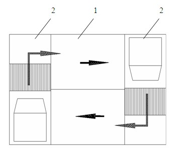
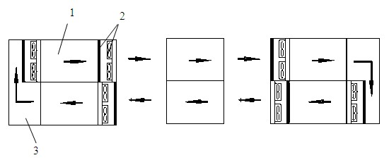
[0031] This cooling solution is specially designed for high-performance computers or large-scale data centers with ultra-high heat density cooling solutions. The ultra-high heat density cooling system in this embodiment is a multi-rack and multi-air conditioner series fully enclosed air cooling circulation system (hereinafter referred to as: cooling circulation system). The cooling circulation system includes air conditioning equipment, and the air conditioning equipment includes Two-layer cooling cycle, refrigeration host and cooling terminal. The first layer of cooling cycle includes pumps, air-fluid heat exchangers, and fluid-fluid heat exchangers. The cooling cycle uses volatile working fluids to transfer heat; the second layer of cooling cycles uses A cold water system that transfers heat from a fluid-fluid heat exchanger to the environment, or a vapor compression system that transfers heat from a fluid-fluid heat exchanger to the environment. The cooling host and the cool...

Embodiment 2

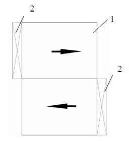
[0044] like figure 2 , 4 As shown, the difference between this embodiment and the foregoing embodiment 1 is that when the rack server 1 has sufficient air volume, the cooling terminal 2 can cancel the fan and only retain the heat exchanger. Cooling terminal 2 is arranged as Image 6 As shown (but without fan 57), after the cryogenic liquid enters the cooling terminal 2 through the pipeline, it first passes through the flow regulating valve 58 (the flow regulating valve 58 is used to control the flow of the cryogenic liquid), and the cryogenic liquid comes out of the flow regulating valve 58 and then Enter the air-fluid heat exchanger 56, in the air-fluid heat exchanger 56 due to absorbing the heat of the air side of the air-fluid heat exchanger 56, a phase change process occurs from liquid to gas, in the air-fluid heat exchanger 56 The outlet low-temperature fluid has been transformed into high-temperature gas, and flows out of the cooling terminal 2 through the pipeline sy...

Embodiment 3

[0048] As a more preferred embodiment, the cooling terminal in this embodiment adopts a microchannel heat exchanger, and the thickness of the microchannel heat exchanger can be more than 70% smaller than common radiators such as copper tube fin heat exchangers, etc. The air resistance of the micro-channel heat exchanger is also much smaller, so the thickness of the cooling terminal in this embodiment can be made very small, thereby further saving valuable space in the machine room.


PUM


Abstract

The invention relates to an ultrahigh heat density cooling system, which comprises air conditioning equipment, wherein the air conditioning equipment comprises two layers of cooling cycles; a refrigerating host machine and a cooling terminal are arranged separately; and the cooling terminal and cooled equipment form a totally-enclosed air circulating system. The refrigerating host machine and cooling terminal equipment are arranged separately, and the cooling terminal and cooled equipment form the totally-enclosed air circulating system, so that the air supply distance is shorter when the cooling terminal is closer to the cooled equipment, and heat and mass transfer with the outside does not exist. By adopting the ultrahigh heat density cooling system, cooling effect is remarkably enhanced, the system runs without being interfered by external factors and a machine room environment is not influenced; furthermore, the cooling terminal is separated from the refrigerating host machine, sothat vibration produced by a compressor is avoided, and noise is greatly lowered.

Description

technical field [0001] The invention relates to a cooling system, in particular to an ultra-high heat density cooling system. Background technique [0002] High-performance computers (also known as supercomputers) for scientific computing have developed from petaflops to petaflops. At the same time, Internet information service companies have successively established huge data centers. With the continuous growth of the scale of two typical supercomputing platforms, computing centers and data centers, the demand for ultra-high heat density cooling systems is becoming more and more urgent. [0003] The current cooling strategy for ultra-high heat density cabinets or blade servers is to set a special high heat density area, set a limited special area in the computer room to provide strong heat dissipation, and limit the high heat density cabinets to this area. When a dedicated high thermal density zone is identified, users can apply specific high thermal density technology in...

Claims


Application Information

Patent Timeline
IPC IPC(8): G06F1/20H05K7/20
Inventor 王锋丁良尹靳世文
Owner EMERSON NETWORK POWER CO LTD
Why Eureka
Try Eureka