System and method for monitoring quality of optical link of passive optical network

A passive optical network and quality monitoring technology, applied in the field of passive optical networks, can solve the problems of laborious, unable to measure once, and difficult to quickly understand the end-to-end quality status of links, so as to save fault location time and save Workload and maintenance costs, and the effect of preventing optical path failures

Active Publication Date: 2014-05-28
CHINA TELECOM CORP LTD
View PDF3 Cites 0 Cited by
  • Summary
  • Abstract
  • Description
  • Claims
  • Application Information

AI Technical Summary

Problems solved by technology

The disadvantage of this method is that it is impossible to measure the link quality of multiple optical fibers at once. If you want to detect the status of which optical fiber, you need to manually use an instrument to measure at the test port of the optical cable section. The degree of personnel participation is high, and the operation is time-consuming and laborious. , and it is difficult to quickly understand the end-to-end quality status of all links
In this way, when a fault occurs, since the specific fiber core cannot be determined in advance, the fault measurement and location of each fiber core are performed manually, and the processing speed and complexity are very high.
If the network scale is large or the number of users is large, then this artificial and passive optical link monitoring and obstacle handling method is not only extremely inefficient, but also consumes huge manpower and material resources.

Method used


Image

  • System and method for monitoring quality of optical link of passive optical network
  • System and method for monitoring quality of optical link of passive optical network
  • System and method for monitoring quality of optical link of passive optical network

Examples


Embodiment Construction

[0033] In order to make the object, technical solution and advantages of the present invention clearer, the present invention will be described in further detail below in conjunction with specific embodiments and with reference to the accompanying drawings.

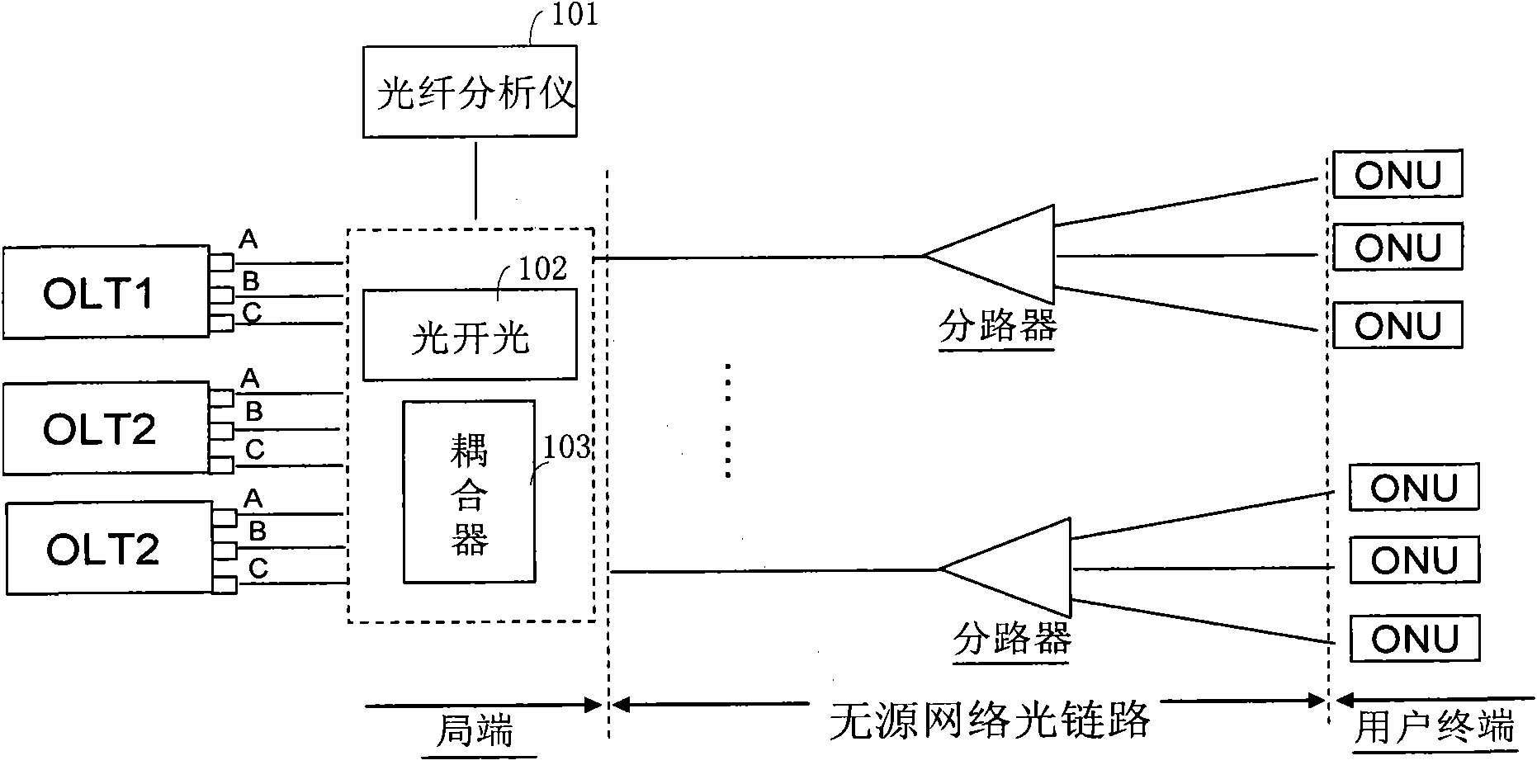
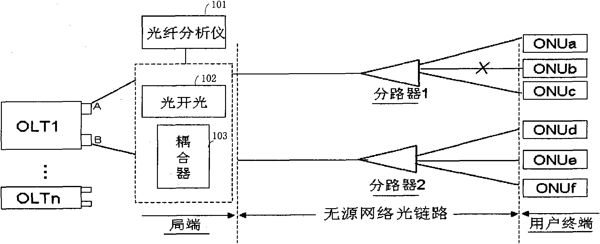
[0034] see figure 1 As shown, the passive optical network optical path quality monitoring system of the embodiment of the present invention mainly includes: a fiber grating (not shown in the figure), an M×N full-cross optical switch 102, a coupler 103, and an optical fiber analyzer 101; wherein,

[0035] The fiber grating is arranged at the terminal position of each optical link of the passive optical network, and is used for increasing the reflection event intensity of the test light and filtering out light of other wavelengths other than the test light wavelength in the test band. The fiber grating can be set in the ONU or on the optical link between the splitter and the ONU.

[0036] One end of the M×N full-cross opti...


PUM


Abstract

The invention discloses a system and a method for monitoring the quality of an optical link of a passive optical network. Optical bragg gratings are arranged at the termination positions of each optical link of the passive optical network. An optical fiber analyzer is arranged on the local sides of the optical links, and is connected with each optical link of the passive optical network by a full-cross optical switch and a coupler. The method comprises that: the optical fiber analyzer produces and transmits testing light with testing wavelengths for link monitoring, and the testing light passes through the full-cross optical switch and the coupler, is periodically coupled with light, with working wavelengths, emitted from each port of each optical line terminal (OLT) equipment on the local side in turn, and is output to the optical links of the ports; and the optical fiber analyzer detects the fed-back testing light, extracts testing light data, compares the acquired data of a current port with own normal state data values of the port, and reports alarming and performance events if a variation exceeds a preset redundancy threshold. In the system and the method, centralized and automatic one-stop periodical monitoring is realized in the passive optical network.

Description

technical field [0001] The invention relates to the technical field of passive optical networks, in particular to a system and method for monitoring the quality of an optical path of a passive optical network. Background technique [0002] The composition of the passive optical network (PON, Passive-Optical-Network) mainly includes: the optical line terminal (Optical Line Terminal-OLT) at the central office, the optical network unit (ONU, Optical Network Unit) or the optical network terminal (ONT, Optical Network Terminal), and an optical distribution network (ODN, Optical Distribution Network) for connecting them. Among them, the ODN does not contain any electronic devices and electronic power sources, and is composed of passive devices such as optical fibers, optical cables, and optical splitters (Splitter), and does not require expensive active electronic devices. [0003] Normally, the active optical access network technology is a point-to-point optical fiber transmissi...

Claims


Application Information

Patent Timeline
Patent Type & Authority Patents(China)
IPC IPC(8): H04B10/071H04Q11/00H04B10/079
Inventor 俞韶桢赵洪波赵敬谦冯晓冬唐建军薄明霞贾海燕
Owner CHINA TELECOM CORP LTD
Why Eureka
Try Eureka