
LED constant-current driver with boosting function

A constant current driver and function technology, applied in the output power conversion device, the conversion of DC power input to DC power output, instruments, etc., can solve the problems of no boost, energy waste, and inability to use constant voltage power supply for power supply, etc. The effect of avoiding drive current, preventing battery life from shortening, and high practical value

Inactive Publication Date: 2013-08-07
常州文通光电有限公司
View PDF2 Cites 0 Cited by
  • Summary
  • Abstract
  • Description
  • Claims
  • Application Information

AI Technical Summary

Problems solved by technology

Therefore, it cannot be powered by a constant voltage power supply.
Although the other LED driver is a constant current drive, it has no boost function, and a large part of the energy is wasted on the current limiting resistor connected to the driven LED.

Method used


Image

  • LED constant-current driver with boosting function
  • LED constant-current driver with boosting function

Examples


Embodiment Construction

[0016] The present invention is described in further detail below in conjunction with the embodiment that accompanying drawing provides.

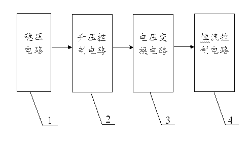
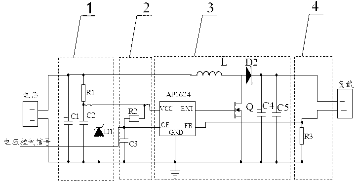
[0017] Such as figure 1 , 2 As shown, the LED constant current driver with boost function of the present invention includes a voltage stabilizing circuit 1 connected between the power supply and the load, a boost control circuit 2, a voltage conversion circuit 3 and a constant current control circuit 4, the voltage stabilizing The output end of the circuit is electrically connected to the input end of the boost control circuit, the output end of the boost control circuit is electrically connected to the input end of the voltage conversion circuit, and the output end of the voltage conversion circuit is electrically connected to the constant current control circuit.

[0018] Such as figure 2 As shown, the output terminal of the chip AP1624 is the EXT terminal, the input terminal is the VCC terminal, the control terminal is the CE terminal...


PUM


Abstract

The invention discloses an LED constant-current driver with a boosting function, which comprises a voltage-stabilizing circuit, a boosting control circuit, a voltage changing circuit and a constant-current control circuit which are connected between a power source and a load. The power source, the voltage-stabilizing circuit, the boosting control circuit, the voltage changing circuit, the constant-current control circuit and the load are electrically connected sequentially. The invention can meet the expected requirement for brightness, can ensure the consistency in brightness and chroma of each LED, can avoid the driving current from surpassing the maximum rate current, and has excellent reliability. The invention also has the advantages of capability of boosting the input voltage to theneeded voltage and simple structure.

Description

technical field [0001] The invention relates to an LED driver, in particular to an LED constant current driver with a boost function. Background technique [0002] Since LED (Light Emitting Diode) is a semiconductor device with sensitive characteristics and has negative temperature characteristics, it is necessary to stabilize its working state during application, thus the concept of driving is born. LED devices have almost strict requirements on driving power. Unlike ordinary incandescent bulbs, LEDs can be directly connected to 220V AC. LED is driven by low voltage, so it is necessary to design a complex conversion circuit, and LED lights for different purposes need to be equipped with different power adapters. As customers have higher and higher requirements for efficiency conversion, effective power, constant current accuracy, power supply life, and electromagnetic compatibility of LED drive power supplies, these factors must be considered comprehensively when designing...

Claims


Application Information

Patent Timeline
Patent Type & Authority Patents(China)
IPC IPC(8): H05B37/02H02M3/155
Inventor 齐本胜苗红霞牛玉祥翟潘飞曾鹏飞
Owner 常州文通光电有限公司
Learn More