Spinal column dynamic connection rod

A dynamic connection, spine technology, applied in the direction of internal fixator, internal bone synthesis, fixator, etc., can solve the problems of unable to provide dynamic stability of the spine, weak rigidity of the fixation device, inconvenient for surgical implantation, etc., to reduce spinal nerve pressure. , Simple structure, provides the effect of spinal stability

Inactive Publication Date: 2011-06-29
SHANGHAI MICROPORT ORTHOPEDICS
View PDF7 Cites 14 Cited by
  • Summary
  • Abstract
  • Description
  • Claims
  • Application Information

AI Technical Summary

Problems solved by technology

The structure of this prior art implant is also relatively complicated, requires more assembly steps, and is inconvenient for surgical implantation
[0008] Prior art patent document CN100409820C proposes a bioflexible spinal fixation device with shape memory alloy, which discloses a bioflexible spinal fixation device with shape memory alloy, although the fixation device can obtain good flexibility, but The rigidity of the fixation device is weak, the stability is not strong, and it cannot provide sufficient dynamic stability of the spine

Method used


Image

  • Spinal column dynamic connection rod
  • Spinal column dynamic connection rod
  • Spinal column dynamic connection rod

Examples


Embodiment Construction

[0038] Preferred embodiments of the present invention are described in detail below with reference to the accompanying drawings.

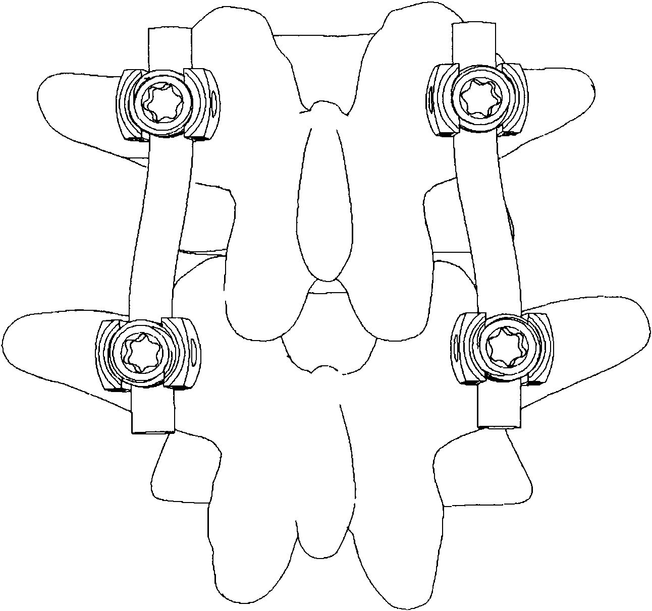
[0039] figure 1 is a schematic diagram of a prior art connecting rod applied to the spine. In the prior art, the connecting rods of the pedicle screw system for spinal fusion surgery are usually solid metal connecting rods, such as figure 1 As shown; such a solid metal connecting rod has no elasticity. This strong metal connecting rod secures the fused segments of the spine relative to each other. However, the relative fixation of the fused segment will lead to the concentration of stress to the adjacent vertebral body; at the same time, the loss of the range of motion of the fused segment will lead to the increase of the range of motion of the adjacent segment to compensate for the mobility of the fused segment, resulting in Abnormalities in the biomechanical environment of adjacent segments; changes in the biomechanical environment can eventua...


PUM


Abstract

The invention provides a spinal column dynamic connection rod, comprising an upper connection part, a lower connection part and an elastic piece, wherein the upper connection part and the lower connection part are connected with each other via the elastic piece. The spinal column dynamic connection rod is characterized in that: the upper connection part, the lower connection part and the elastic piece are integrally formed; the elastic piece is provided with an elastic hole; and an elastic groove is formed on an external periphery of the elastic piece. The spinal column dynamic connection rodprovided by the invention can realize stability of the spinal column and keep the normal physiological movement of the spinal column with a simple structure.

Description

technical field [0001] The invention relates to the technical field of orthopedic implants, in particular to a spinal dynamic connecting rod. Background technique [0002] When the intervertebral disc degenerates or the facet joint slips or degenerates, it will cause the loss of intervertebral height and the instability of the rear structure, which will lead to narrowing of the intervertebral foramen and vertebral foramina; and this narrowing will compress the spinal nerve or nerve root, causing the patient's lumbar Symptoms such as leg pain and numbness seriously affect the patient's quality of life. [0003] The main method known to solve this problem is the intervertebral fusion, by which the intervertebral height can be maintained and the stress on the neural structures can be reduced. At present, the pedicle screw system (connecting rods in the system are usually solid metal connecting rods), fusion cages and various plate-shaped devices are mainly used for strong fixa...

Claims


Application Information

Patent Timeline
Patent Type & Authority Applications(China)
IPC IPC(8): A61B17/70
Inventor 田芳李雷刘道志
Owner SHANGHAI MICROPORT ORTHOPEDICS
Why Eureka
Try Eureka