
Transmission mechanism for passive edge folding device

A technology of folding-in edge device and transmission mechanism, which is applied in looms, textiles, textiles and papermaking, etc., and can solve the problems of high processing precision of conjugate cams, large space occupied by cam components, and large moment of inertia of conjugate cams, etc. , to achieve the effect of saving installation space, low processing precision requirements, and small volume

Inactive Publication Date: 2011-06-29
常熟纺织机械厂有限公司
View PDF7 Cites 14 Cited by
  • Summary
  • Abstract
  • Description
  • Claims
  • Application Information

AI Technical Summary

Problems solved by technology

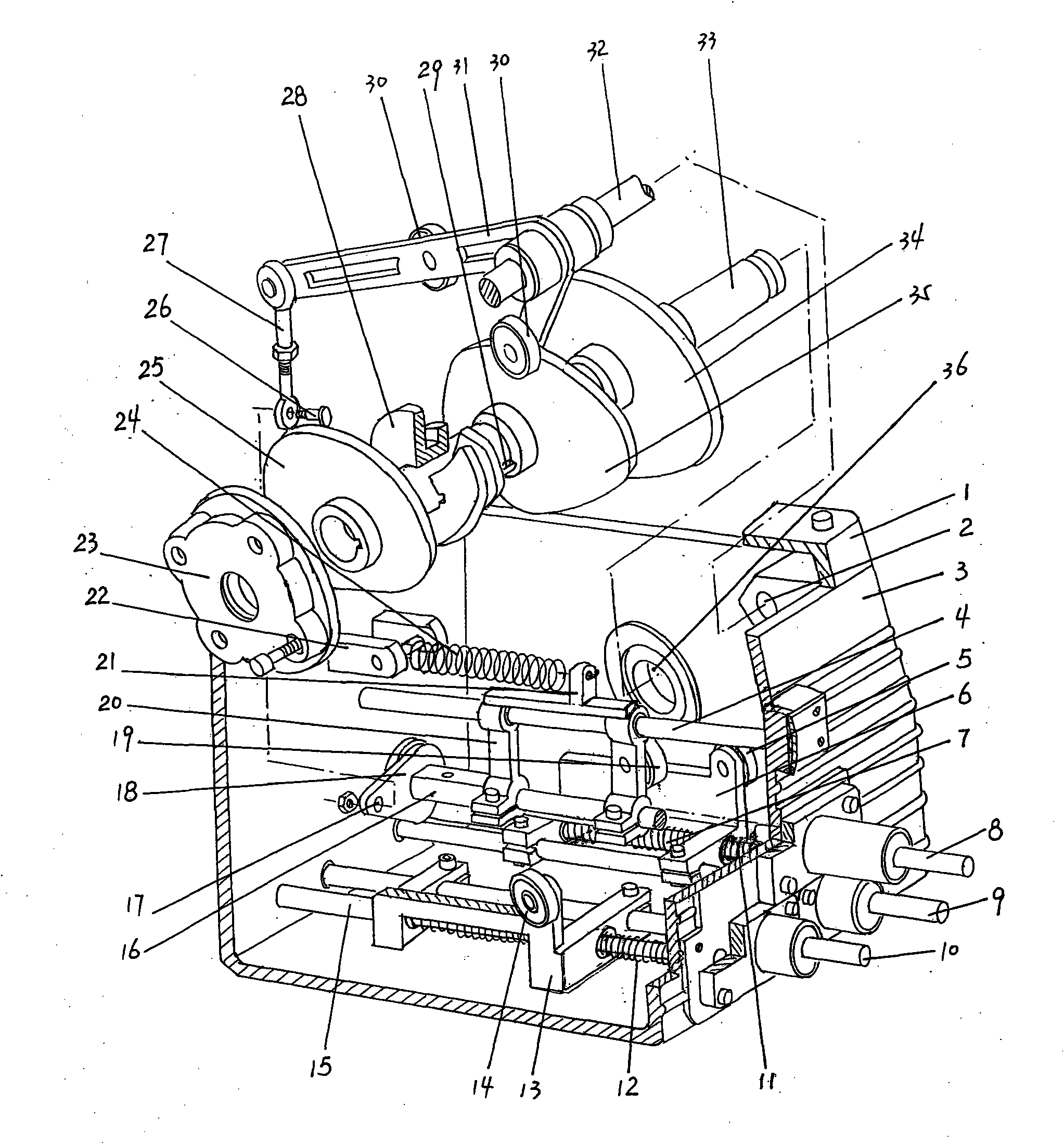
In the transmission mechanism of the folding-in device currently on the market, the cam components used to control the movement of the above three axes are mostly positive conjugate cams, such as the "folding-in device" disclosed in the Chinese utility model patent authorization announcement number CN2646167Y The presser foot shaft conjugate cam, the scissor shaft conjugate cam, and the hook needle shaft conjugate cam in ", these three conjugate cams are all composed of two cam pieces, and are passed through a pair of rollers that match the two cam pieces. To jointly control the movement law of a shaft, the problems of this structure are: firstly, the machining accuracy of the conjugate cam is high, and the cost is also high; secondly, the moment of inertia of the conjugate cam is large when it rotates; thirdly, the entire cam The space occupied by the components is large, and the space inside the case of the folded-in device is very tight, which is not convenient for installation and maintenance
[0003] For the above-mentioned prior art, the applicant thinks that it is necessary to explore and try for improvement. For this reason, the applicant has searched a large number of patent documents and non-patent literature, but there is no possible solution in the published documents. Based on the technical enlightenment for reference, the technical solutions to be introduced below are produced under this background

Method used


Image

  • Transmission mechanism for passive edge folding device
  • Transmission mechanism for passive edge folding device

Examples


Embodiment Construction

[0013] In order to enable the examiners of the patent office, especially the public, to understand the technical essence and beneficial effects of the present invention more clearly, the applicant will describe in detail the following in the form of examples, but none of the descriptions to the examples is an explanation of the solutions of the present invention. Any equivalent transformation made according to the concept of the present invention which is merely formal but not substantive shall be regarded as the scope of the technical solution of the present invention.

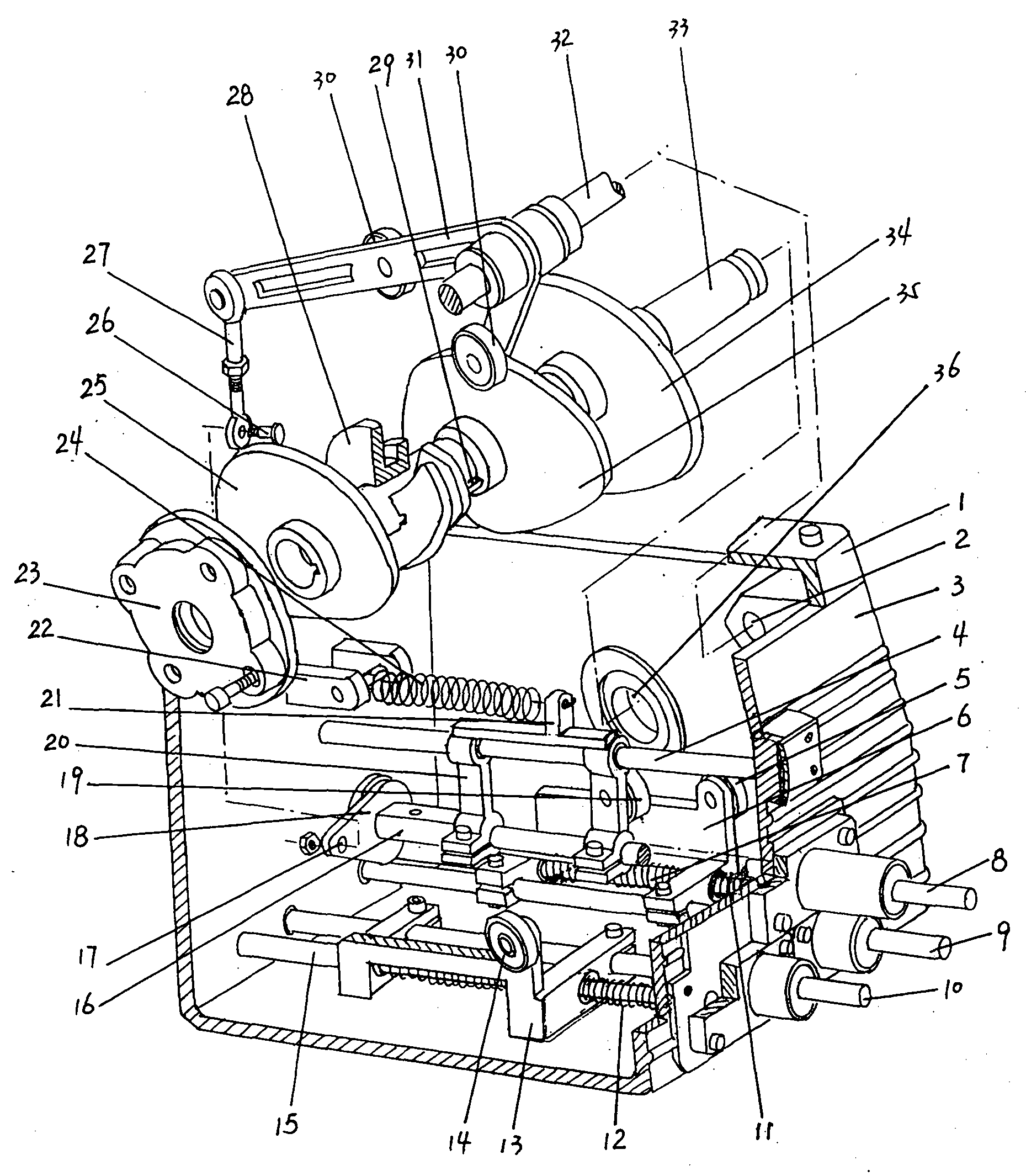
[0014] see figure 1 , a transmission mechanism of a passive tuck-in device, the tuck-in device includes a casing 3 and a cover 1 sealed at the upper opening of the casing 3, the transmission mechanism of the tuck-in device includes a cam Axis 33, presser foot shaft cam 34, scissors shaft cam 25, crochet shaft cam 35, presser foot shaft 9, scissors shaft 10, crochet shaft 8, first guide rod 7, first roller sea...


PUM


Abstract

The invention discloses a transmission mechanism for a passive edge folding device, and belongs to the technical field of textile manufacturing machines. The edge folding device comprises a shell and a cover; the transmission mechanism for the edge folding device comprises a cam shaft, a presser foot shaft cam, a shear shaft cam, a looper shaft cam, a presser foot shaft, a shear shaft, a looper shaft, a first guide rod, a first roller seat, a first roller, a first spring, a second guide rod, a second roller seat, a second roller, a second spring, a third guide rod, a third roller seat, a third roller and a third spring. The transmission mechanism has the advantages that: the structure is simple, the requirement on machining accuracy is low and the price is low; the volume is small, the installation space is saved and the transmission mechanism is convenient to maintain; and the whole edge folding device rotates in a more balanced mode.

Description

technical field [0001] The invention belongs to the technical field of textile machinery, and in particular relates to a transmission mechanism of a passive tuck-in device that utilizes a spring for recovery. Background technique [0002] On the shuttleless loom, due to the weft supply method outside the machine, after each weft weaving is completed, the weft yarn must be cut with weft scissors, so that a small section of yarn end will be exposed outside the edge of the cloth. This kind of cloth is called Raw edge cloth. Raw edge cloth looks less beautiful, lacks viewing effect, and the grade is not high, but beautiful, high-grade smooth edge cloth can be processed with the tuck-in edge device. The working principle of the edge folding device is to clamp the weft yarn with a small clip first, then cut the weft yarn at a certain distance from the edge of the selvage, and finally hook the end of the weft yarn into the opening of the edge of the selvage with a hook for weaving...

Claims


Application Information

Patent Timeline
IPC IPC(8): D03D47/27D03D47/40
Inventor 彭晓虹龚月锋卫明
Owner 常熟纺织机械厂有限公司
Learn More