Silt retaining and consolidating method for use in debris flow gully ecological engineering and use thereof

A technology of ecological engineering and debris flow, which is applied in water conservancy projects, sea area engineering, construction, etc., can solve problems such as inability to retain sediment, achieve the effects of improving soil structure, optimizing retention, and reducing sediment sources

Inactive Publication Date: 2011-06-29
INST OF MOUNTAIN HAZARDS & ENVIRONMENT CHINESE ACADEMY OF SCI
View PDF3 Cites 17 Cited by
  • Summary
  • Abstract
  • Description
  • Claims
  • Application Information

AI Technical Summary

Problems solved by technology

This kind of debris flow channel usually has good vegetation coverage, but these vegetation are all ecological restoration from the perspective of ecological structure and landscape, and cannot effectively retain the sediment in the debris flow valley

Method used


Image

  • Silt retaining and consolidating method for use in debris flow gully ecological engineering and use thereof
  • Silt retaining and consolidating method for use in debris flow gully ecological engineering and use thereof
  • Silt retaining and consolidating method for use in debris flow gully ecological engineering and use thereof

Examples


Embodiment 1

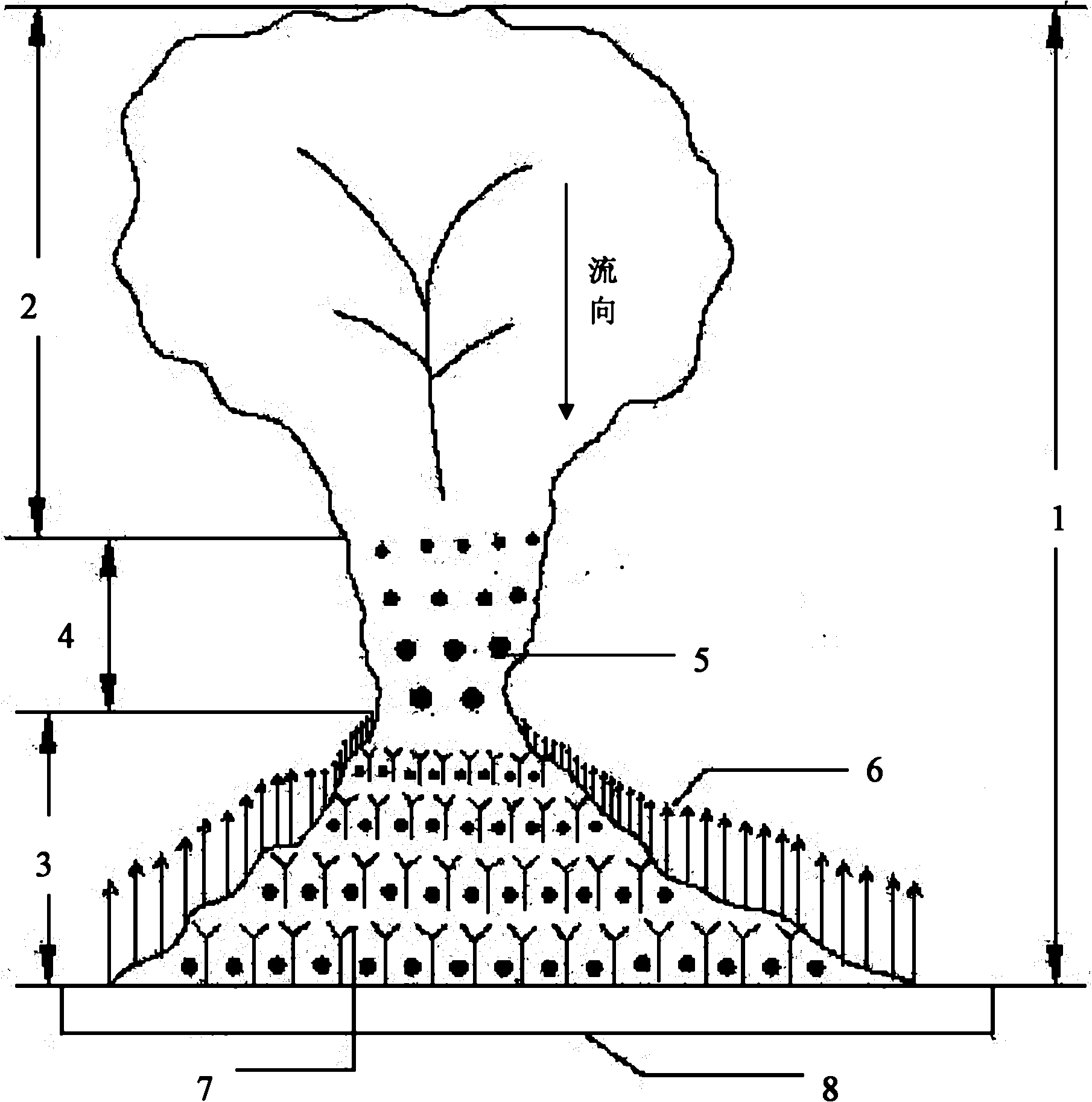
[0025] Such as figure 1 , figure 2 , image 3 , Figure 4 shown. For a valley where a debris flow occurs once in several decades, the ecological engineering sediment retention method of the present invention is directly used in the debris flow valley 1 . The slope of the sediment transport area 4 of the debris flow valley 1 is 10%, and the slope of the bank at the slope foot of the valley 1 is 25 degrees.

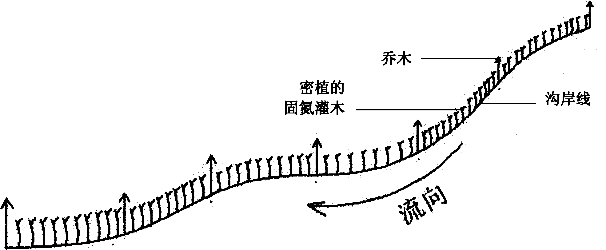
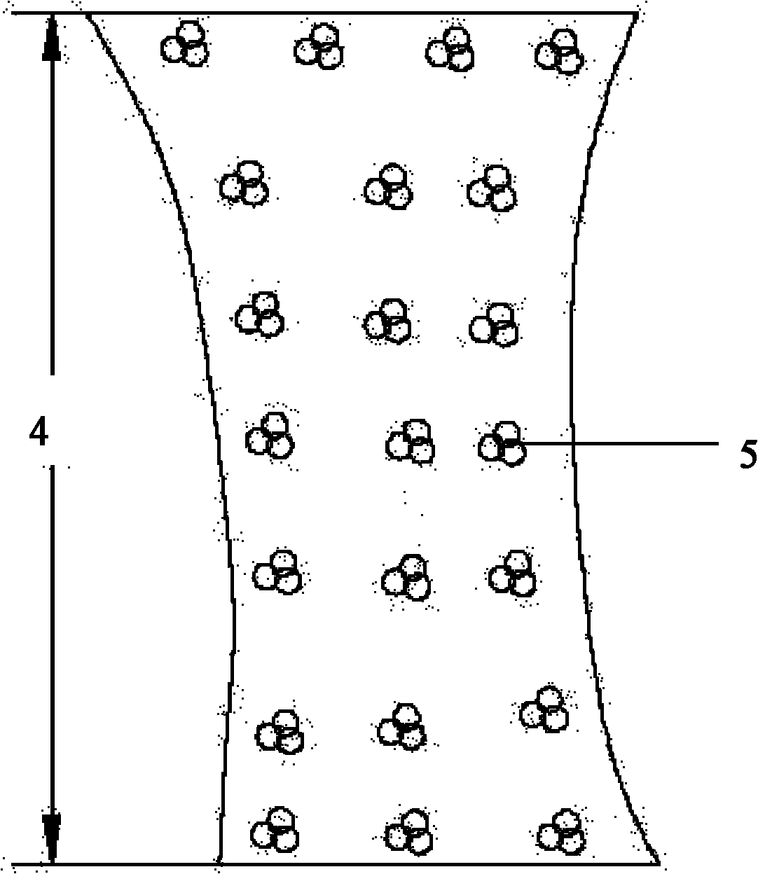
[0026] Plant 8 rows of shrubs 5 to increase the roughness of the ditch bed in the sediment transport area 4 between the debris flow circulation area 2 and the sediment deposition area 3 of the valley 1, and the direction of the rows is perpendicular to the channel to intercept the upstream transport. sediment. The species of shrub 5 was Masangus sangria, and 3 Masangus sangria were planted together to form shrub 5; the height of shrubs 5 was controlled at 0.8-1.2m; The distance between clusters is 1.5m, and the crown width of shrub 5 is controlled at 0.3×0.3m-0.4×0.4...

Embodiment 2

[0030] Such as figure 1 , image 3 , Figure 4 shown. For a valley where debris flow occurs once in a century, the ecological engineering sediment retention method of the present invention is directly used in the debris flow valley 1 . The slope of the sediment transport zone 4 of the debris flow valley 1 is 15%, and the slope of the bank at the slope foot of the valley 1 is 20 degrees.

[0031] In the sediment transport area 4 between the debris flow circulation area 2 and the sediment deposition area 3 in the valley 1, plant 7 rows of shrubs 5 to increase the roughness of the ditch bed. The direction of the rows is perpendicular to the ditch to intercept the upstream transport sediment. The species of bush 5 is selected as bitter thorn, and three bitter thorns are planted together to form bush 5; the height of bush 5 is controlled at 0.8-1.2m; the row spacing between bush 5 is 2.8m, and the same row of The distance between clusters is 1.0m, and the crown width of shrub ...

Embodiment 3

[0035] Such as figure 1 , image 3 , Figure 4 shown. For a valley where a debris flow occurs once in several decades, the ecological engineering sediment retention method of the present invention is directly used in the debris flow valley 1 . The slope of the sediment transport zone 4 of the debris flow valley 1 is 5%, and the slope of the bank at the slope foot of the valley 1 is 30 degrees.

[0036] In the sediment transport area 4 between the debris flow circulation area 2 and the sediment deposition area 3 of the valley 1, plant 9 rows of shrubs 5 to increase the roughness of the ditch bed, and the direction of the rows is perpendicular to the channel to intercept the upstream transport sediment. The species of Shrub 5 are Masangus and Bitterthorn, and 3 Masang plants are planted together to form Shrub 5, and 3 Bitterthorns are planted together to form Shrub 5; the height of Shrub 5 is controlled at 0.8-1.2m; The distance between rows is 3.5m, the distance between bu...


PUM


Abstract

The invention discloses a silt retaining and consolidating method for use in debris flow gully ecological engineering and use thereof. The method comprises: planting a plurality of brush woods for increasing the roughness of the gully bed in a silt transfer area between a debris flow flowing area and a silt settling area in the gully; planting bank-protecting and scouring-preventing forest at the foot of a slope of the gully along the bank of the gully for preventing flowing water from scouring the silt on the bank of the gully; and planting arbor and bush combined improved protection forest in the silt settling area to improve the impact strength of soil body. When the method is used, the use of other civil engineering measures in combination is determined according to the occurrence frequency of debris flow. Compared with the prior art, the method can effectively retain, consolidate and improve the silt in the silt transfer area, on the gully slope and in the silt settling area in the debris flow gully, consolidate and improve retained and deposited silt while reducing silt sources, improve the self-stability of the silt soil body in the silt settling area, strengthen the sand control capability of the gully and improve the landscape of the gully.

Description

technical field [0001] The invention relates to a mud-sand control technology in mud-rock flow prevention and control, in particular to an ecological engineering mud-sand retention method for mud-rock flow valleys and its application. Background technique [0002] In recent years, with the in-depth development of China's western region, the development of cascade hydropower projects in the upper reaches of the Yangtze River and the construction of large-scale railway and highway projects have caused damage to unstable mountains in mountainous areas, and after the "5.12" Wenchuan Earthquake, a large number of non-debris flows The ditch turns into a low-frequency or high-frequency debris flow ditch, which increases the ability of the ditch to input sediment into the main river, resulting in increased river sediment, reduced reservoir capacity, and even blocking the river to form a barrier lake, submerging farmland, railways, roads and other buildings along the river. things. ...

Claims


Application Information

Patent Timeline
Patent Type & Authority Applications(China)
IPC IPC(8): E02B3/04
Inventor 王道杰崔鹏林勇明陈晓清游勇葛永刚洪勇
Owner INST OF MOUNTAIN HAZARDS & ENVIRONMENT CHINESE ACADEMY OF SCI
Why Eureka
Try Eureka