Eureka AIR delivers breakthrough ideas for toughest innovation challenges, trusted by R&D personnel around the world.

Box beam composite piece with metal joint and manufacturing method thereof

A technology of metal joints and box girders, which is applied in the direction of final product manufacturing, sustainable manufacturing/processing, wind power generation, etc., can solve the problems of inconvenience and lack of suitable structure for general products, and achieve simple production, difficult quality control, and production easy effect

Inactive Publication Date: 2011-06-29
柯正忠
View PDF0 Cites 0 Cited by
  • Summary
  • Abstract
  • Description
  • Claims
  • Application Information

AI Technical Summary

Problems solved by technology

[0006] It can be seen that the above-mentioned existing box girder obviously still has inconvenience and defects in structure and use, and needs to be further improved urgently.
In order to solve the above-mentioned problems, the relevant manufacturers have tried their best to find a solution, but for a long time no suitable design has been developed, and the general product has no suitable structure to solve the above-mentioned problems. This is obviously the relevant industry. Urgent problem

Method used


Image

  • Box beam composite piece with metal joint and manufacturing method thereof
  • Box beam composite piece with metal joint and manufacturing method thereof
  • Box beam composite piece with metal joint and manufacturing method thereof

Examples


Embodiment Construction

[0070] In order to further explain the technical means and effects adopted by the present invention to achieve the intended purpose of the invention, below in conjunction with the accompanying drawings and preferred embodiments, the concrete implementation of the box girder composite parts containing metal joints and its manufacturing method proposed according to the present invention Mode, structure, feature and effect thereof are as follows in detail.

[0071] The aforementioned and other technical contents, features and effects of the present invention will be clearly presented in the following detailed description of preferred embodiments with reference to the drawings. Through the description of the specific implementation mode, when the technical means and functions adopted by the present invention to achieve the predetermined purpose can be obtained a deeper and more specific understanding, but the accompanying drawings are only for reference and description, and are not...


PUM


Abstract

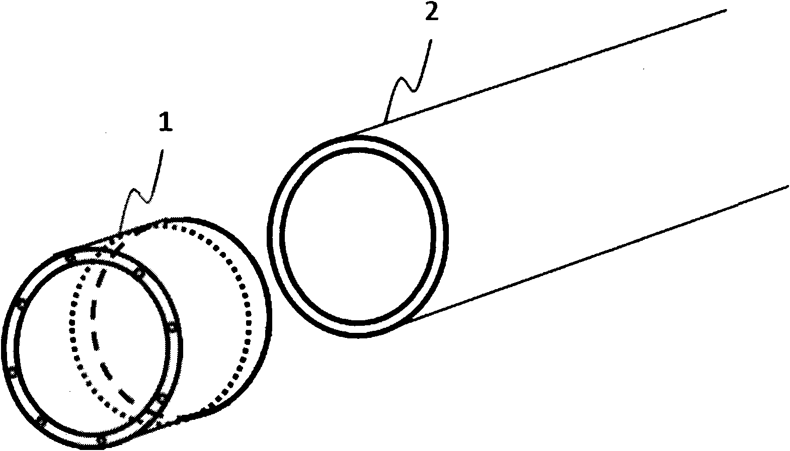
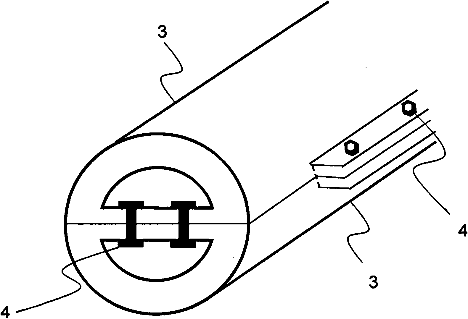
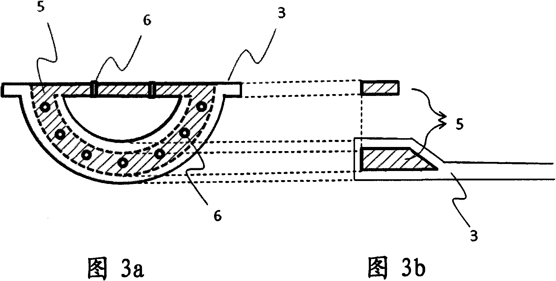
The invention relates to a box beam composite piece with a metal joint and a manufacturing method thereof. The box beam composite piece with the metal joint comprises two groove-shaped composite beams with lugs, wherein the tail end of each groove-shaped beam is provided with an annular metal end piece; and one part of the end piece is coated in a fiber composite material, and the other part of the end piece is exposed for the combination of upper and lower groove-shaped composite beams. The two groove-shaped beams with the lugs are combined to fixedly form an integrated box beam in modes of bolt fastener locking, gluing or bolt fastener locking and gluing at the laminated protruding lugs and the exposed metal end pieces. The manufacturing method comprises the following steps of: ensuring that the composite material passes through the annular metal end piece on a groove-shaped die with a lug, inversely folding and putting on a groove-shaped composite laminated layer; and curing together at room temperature or a high temperature.

Description

technical field [0001] The invention relates to a box girder composite part containing metal joints and its manufacturing method, in particular to a design and manufacturing method of a composite box girder, which can be applied to the wings of a wind power generator, especially a wind power generator The box girder inside the airfoil, and the box girder is a box girder made of a laminated wing structure with box girder composite materials. Background technique [0002] By the way, in response to the increasing shortage of energy resources today, wind power generation is getting more and more attention, but the most important thing for wind power generation is the wind turbine blades. The reason is that without wind turbine blades, wind power generators cannot Rotation, and the requirements of wind turbine blades are light weight and high structural strength. However, in the existing conventional technology, light weight means weak strength, and high structural strength mean...

Claims


Application Information

Patent Timeline
Patent Type & Authority Applications(China)
IPC IPC(8): F03D9/00B29C70/00
CPCY02E10/72Y02P70/50
Inventor 柯正忠
Owner 柯正忠
Why Eureka
Eureka Blog
Learn More