
Steel bar truss floor support plate and lap joint manner thereof

A steel truss and floor deck technology is applied in the field of reinforced truss floor decks and their lap jointing methods, which can solve the problems of long oblique bending, poor lap strength, and unsatisfactory sealing, and achieves increased or decreased strength and improved The effect of flatness

Inactive Publication Date: 2020-11-03
ZHEJIANG WILLING TECH
View PDF6 Cites 0 Cited by
  • Summary
  • Abstract
  • Description
  • Claims
  • Application Information

AI Technical Summary

Problems solved by technology

This type of lap joint method is easy to leak mud when pouring concrete. The main reasons for the mud leakage phenomenon are as follows: 1. The oblique bend is long, and the edge of the fold is not smooth during the processing of the bottom plate. Wavy edge, so that there is a gap when two adjacent base plates are installed
2. Due to the deviation in the width of the raw material, during the processing of the base plate, there is a deviation between the oblique bending length and the design requirements, and there is a gap when two adjacent base plates are connected
3. During the installation process, the two adjacent bottom plates are not tensioned, and there is a gap between the two bottom plates
4. Poor lap strength
The overlapping method has high requirements on the precision of the inner connecting plate 13 and the outer connecting plate 12, and the sealing performance is relatively unsatisfactory.

Method used


Image

  • Steel bar truss floor support plate and lap joint manner thereof
  • Steel bar truss floor support plate and lap joint manner thereof
  • Steel bar truss floor support plate and lap joint manner thereof

Examples


Embodiment Construction

[0020] The present invention will be further described in detail below in conjunction with the accompanying drawings and examples. The following examples are explanations of the present invention and the present invention is not limited to the following examples.

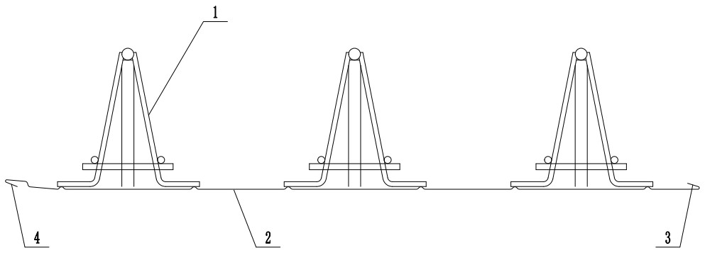
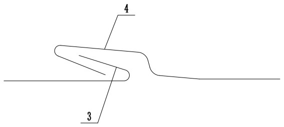
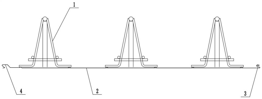
[0021] A steel bar truss floor deck, comprising a steel bar truss 1 and a bottom plate 2, the steel bar trusses 1 are evenly distributed on the bottom plate 2, and the two ends of the bottom plate 2 are respectively provided with lap lock tongues 3 and lap lock buckles 4 , the overlapping locking tongue 3 is formed by bending, and is in two consecutive U-shaped shapes, including an upper overlapping storage section 5 and a lower overlapping storage section 6, and the overlapping locking buckle 4 is formed by bending , including the locking section 7 , the upper closing section 8 , the side closing section 9 and the lower closing section 10 .

[0022] A method of overlapping steel truss floor decks. The bottom plates...


PUM


Abstract

The invention provides a steel bar truss floor support plate and a lap joint manner thereof, and belongs to the technical field of steel bar truss floor support plates. A lap joint spring bolt and a lap joint lock catch are arranged at two ends of a bottom plate respectively, wherein the lap joint spring bolt is formed by bending and is in a continuous two-U shape, and comprises an upper lap jointmaterial storage section and a lower lap joint material storage section, and the lap joint lock catch is formed by bending and sequentially comprises a lock catch section, an upper sealing section, aside sealing section and a lower sealing section. According to the lap joint manner of the steel bar truss floor support plate, the bottom plates of every two adjacent steel bar truss floor support plates are subjected to clamping and lap joint through the lap joint spring bolt and the lap joint lock catch, and an upper material storage cavity and a lower material storage cavity are formed between the lap joint spring bolt and the lap joint lock catch after lap joint is performed. The lap joint strength is good, the lap joint stability of the steel bar truss floor support plate is greatly improved, the lap joint sealing performance is good, the upper material storage cavity and the lower material storage cavity are formed between the lap joint spring bolt and the lap joint lock catch after lap joint is performed, and mud leakage is avoided.

Description

technical field [0001] The invention relates to the technical field of steel truss floor decks, in particular to a steel bar truss floor deck and an overlapping method thereof. Background technique [0002] The truss formed by using steel bars as the upper chord, lower chord and web members and connected by resistance spot welding is called steel truss, and the composite load-bearing plate that is connected by steel truss and bottom plate by resistance spot welding is called steel truss floor deck. The main advantages of the reinforced truss floor deck: the mechanized production is realized, which is conducive to the uniform arrangement of steel bars and the uniform thickness of the concrete cover, which improves the construction quality of the floor. Accelerate the construction progress, increase the construction safety guarantee, realize civilized construction, and meet the national energy conservation and environmental protection requirements. When in use, the bottom pla...

Claims


Application Information

Patent Timeline
IPC IPC(8): E04B5/40E04B1/61
CPCE04B5/40E04B1/6137
Inventor 朱贤杨桂灿陈英豪
Owner ZHEJIANG WILLING TECH
Learn More