Heat exchanger

A technology of heat exchange device and exchange body, which is applied in heat exchange equipment, lighting and heating equipment, instruments, etc., can solve the problems of electronic emission element performance change, element performance change, unclear mechanism, etc., and achieve excellent heat exchange performance, The effect of suppressing the decrease in heat exchange performance and improving heat exchange performance

Inactive Publication Date: 2011-06-29
SHARP KK
View PDF6 Cites 4 Cited by
  • Summary
  • Abstract
  • Description
  • Claims
  • Application Information

AI Technical Summary

Problems solved by technology

That is, toluene or ethanol used as an organic solvent when producing an electron emitting element, if the solvent is not volatilized sufficiently, the performance of the electron emitting element will fluctuate greatly and deteriorate.
In addition, when the manufactured electron emission element is expo...

Method used


Image

  • Heat exchanger
  • Heat exchanger
  • Heat exchanger

Examples


Embodiment approach 1

[0062] Below, based on figure 1 or Figure 9 Embodiment 1 of the present invention will be described.

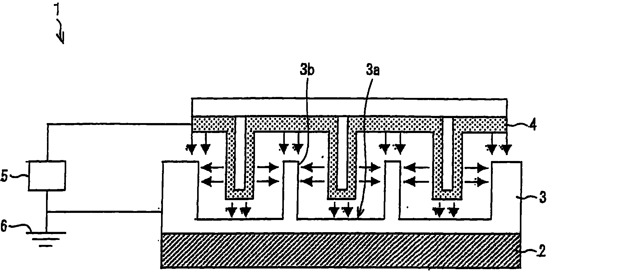
[0063] It should be noted that the structure described below is only a specific example of the present invention, and the present invention is not limited thereto. figure 1 It is a cross-sectional view of a preferable example of the heat generating body radiator (cooling device) 1 of this embodiment.

[0064] The heating element cooling device 1 is a device that radiates the heat emitted by the heating element 2 to the outside, and includes: a heat sink (heated exchange body) 3; an electron emission element 4; a power supply (second voltage applying unit) 5. The heat sink 3 is made of a conductive material and is in contact with the heating element 2 . Furthermore, the surface 3a of the fin 3 on the side opposite to the heating element 2 is in contact with air, and a plurality of protrusions 3b are formed in at least a part of the area. In addition, the electron emitting...

Embodiment 1

[0091] As an example, in the heating element cooling device of this embodiment, use Figure 4 as well as Figure 5 To illustrate the verification experiment of exothermic effect. In addition, this experiment is an example of implementation, and does not limit the content of this invention.

[0092] In this example, use Figure 4 Experiments were carried out on the heating element cooling device shown. exist Figure 4 A fan 14 is provided in the shown heat exchange device to deliver an air flow to the cooling fins 3 . The heating element 2 as a heat source has a structure to switch heat generation according to the on and off of the switch, and when the switch is turned off, the heating element does not generate heat. In this embodiment, the heating element 2 is turned off (opened) at the same time as the temperature measurement terminal 15 starts measuring the temperature. The temperature measurement terminal 15 measures the surface temperature of the heat sink 3 without ...

Embodiment approach 2

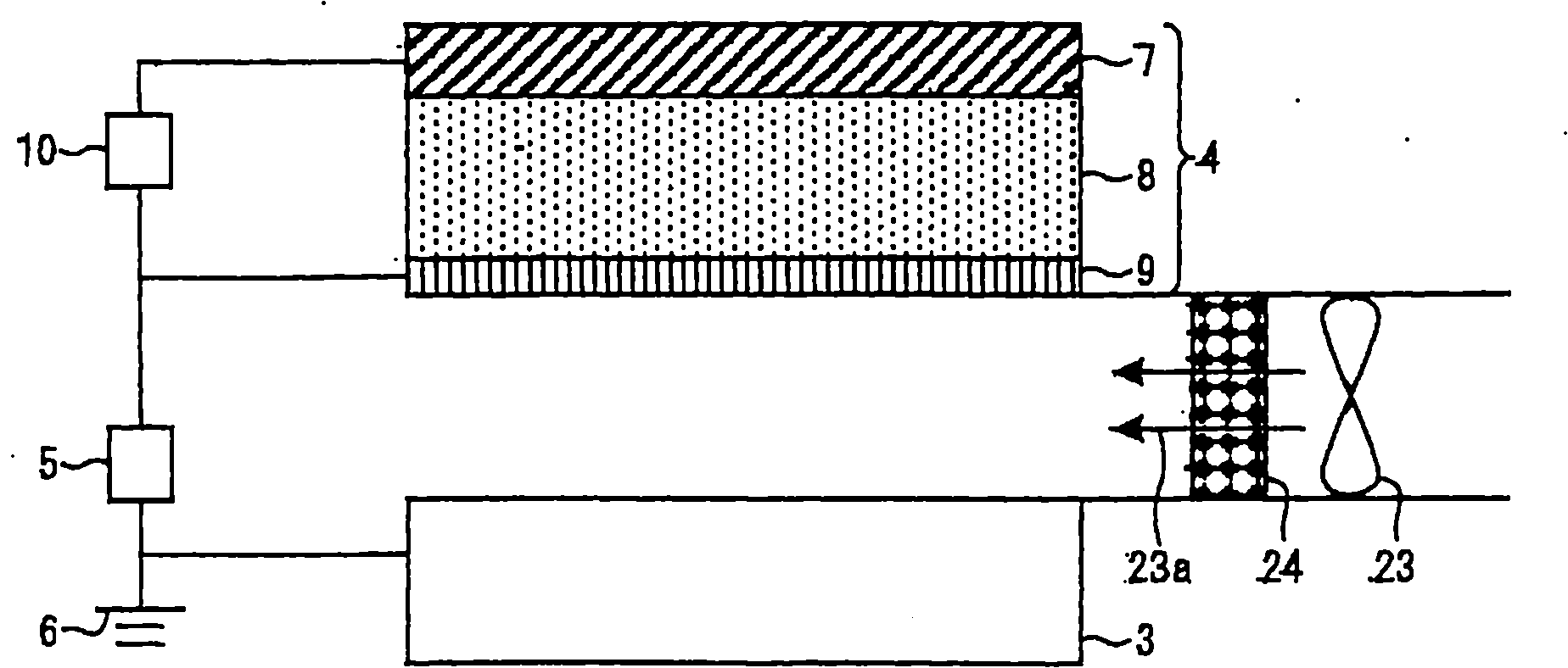
[0098] Regarding other embodiments of the present invention, according to Figure 6 Instructions are given below.

[0099] The basic driving concept of the heating element cooling device of this embodiment is the same as that of the above-mentioned first embodiment, and thus description thereof will be omitted. In the heating element heat dissipation device of this embodiment, the difference from the first embodiment lies in the structure of the electron emitting element. Figure 6 It is a figure which shows the structure of the periphery of an electron emission element in the heat sink heat sink of this embodiment.

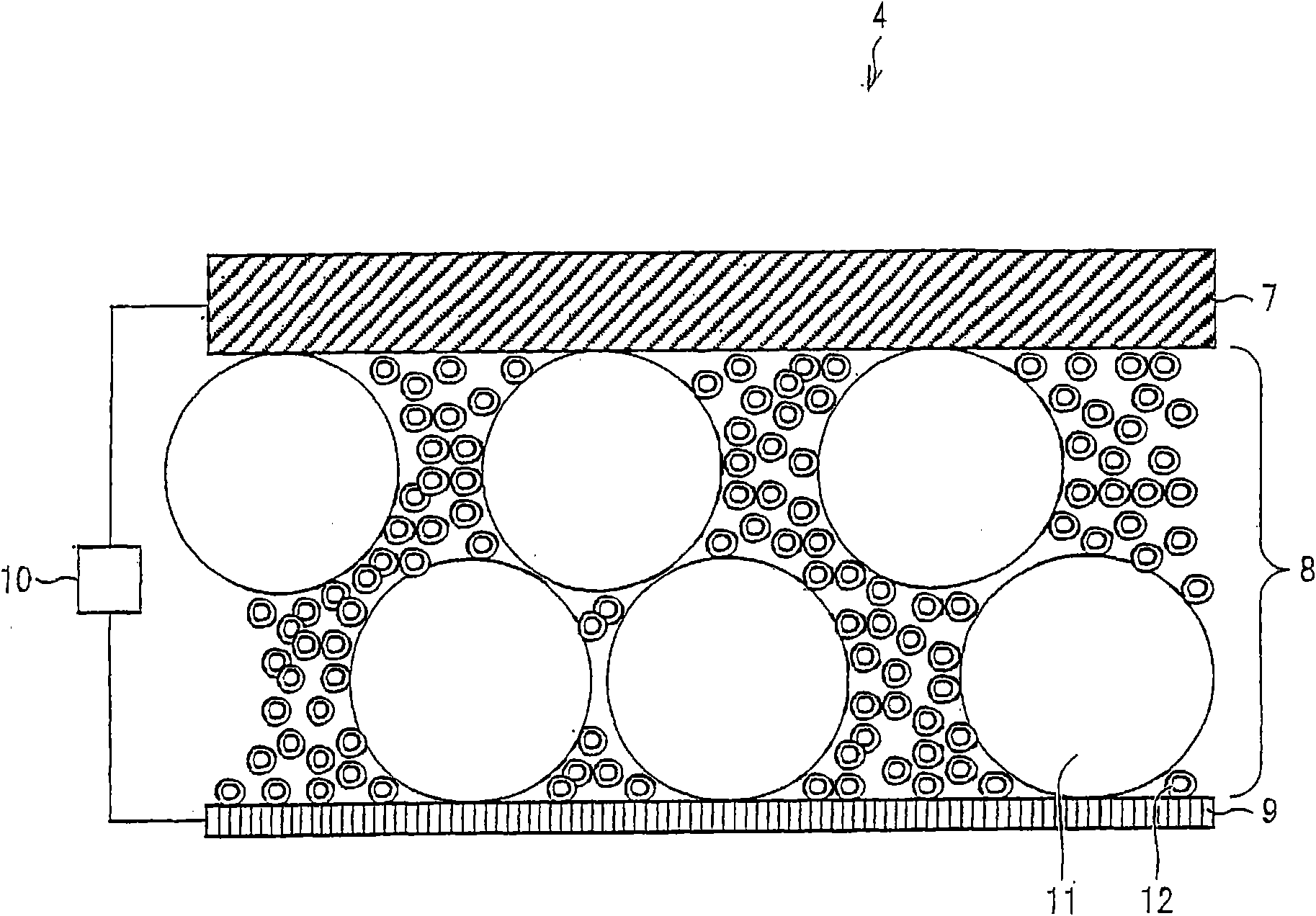
[0100] Such as Figure 6 As shown, the electron emitting element 16 is characterized by being flexible. The electron emission element 16 includes: a flexible base material 17 ; a substrate thin-film electrode 18 ; an electron acceleration layer 8 ; and a thin-film electrode 9 . The substrate film electrode 18 and the film electrode 9 are connected to a power ...


PUM

PropertyMeasurementUnit
The average particle sizeaaaaaaaaaa

Abstract

In order to alleviate reduction in a heat exchange capability and to further improve the heat exchange capability, a heat exchanger of the present invention includes: a heat sink; and an electron emitting element which is provided so as to be separated from the heat sink by a space and which provides electrons to the heat sink via air in the space. The electron emitting element includes: an electrode substrate; a thin-film electrode; a power supply which applies a voltage between the electrode substrate and, the thin-film electrode; and an electron acceleration layer which accelerates electrons inside the electron acceleration layer in response to the voltage applied by the power supply so that the electrons are emitted from the thin-film electrode. The electron acceleration layer is made at least partially of an electric insulating material. The heat exchanger includes an air filter through which air flows onto a surface of the thin-film electrode. This can alleviate reduction in the heat exchange capability, caused by dust that adheres to a surface of the electron emitting element and therefore can attain an excellent heat exchange capability for long periods.

Description

[0001] technology area [0002] The present invention relates to heat exchange devices. Background technique [0003] Conventionally, a heat exchange device described in Patent Document 1 has been proposed as a heat exchange device using an electron emitting element. This heat exchanging device (heating body cooling device 1) includes a heat sink 3 in contact with the heat generating body 2; The electron emission element 4 is provided with an electrode substrate 7; a thin-film electrode 9; a power source 10 for applying a voltage between the electrode substrate 7 and the thin-film electrode 9; and an electron acceleration layer 8, which accelerates electrons inside by applying a voltage through the power source 10, Electrons are emitted from the thin film electrode 9 . At least a part of the electron acceleration layer 8 is made of an insulator substance. Accordingly, the heat exchange performance can be maintained and improved without depending on the structure in which th...

Claims


Application Information

Patent Timeline
IPC IPC(8): H01J17/28
CPCF28F2250/08G06F1/20H05K7/20954
Inventor 岩松正
Owner SHARP KK
Why Eureka
Try Eureka