Radio frequency identification tag antenna suitable for metal surface
A radio frequency identification tag and metal surface technology, applied in the field of radio frequency identification, can solve the problems of reducing the firmness of the antenna, and achieve the effects of simple structure, reduced return loss, and small volume
Inactive Publication Date: 2011-06-29
江苏拓元科技发展有限公司
View PDF4 Cites 20 Cited by
- Summary
- Abstract
- Description
- Claims
- Application Information
AI Technical Summary
Problems solved by technology
However, the size of the ground plane of most PIFAs is larger than that of the dielectric layer, and the dielectric layer is usually an air layer, which reduces the firmness of the antenna. In addition, the impedance of this type of antenna is generally 50 ohms, which is not suitable for RFID tag antennas
Method used
View moreImage
Smart ImageViewing Examples

Examples
Embodiment Construction
Login to View More PUM
| Property | Measurement | Unit |
|---|---|---|
| Thickness | aaaaa | aaaaa |
Abstract
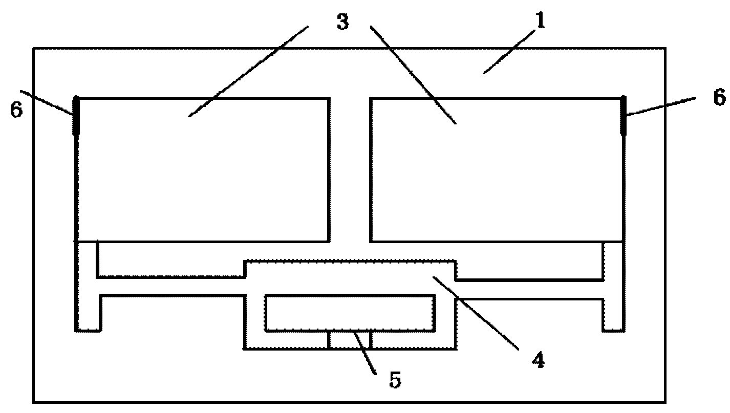
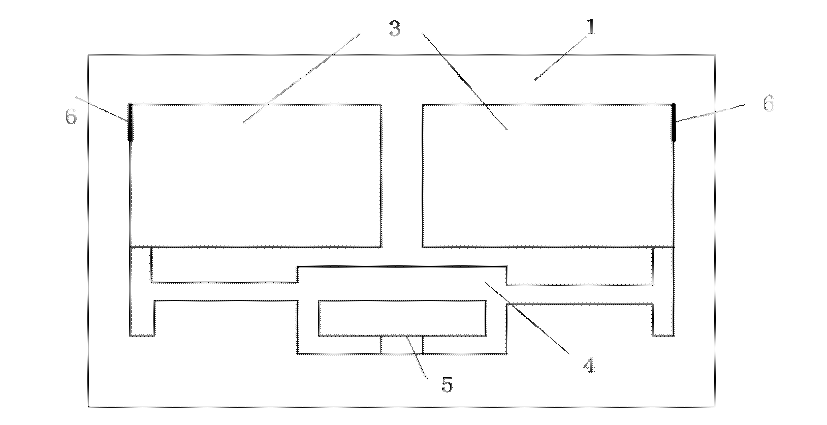
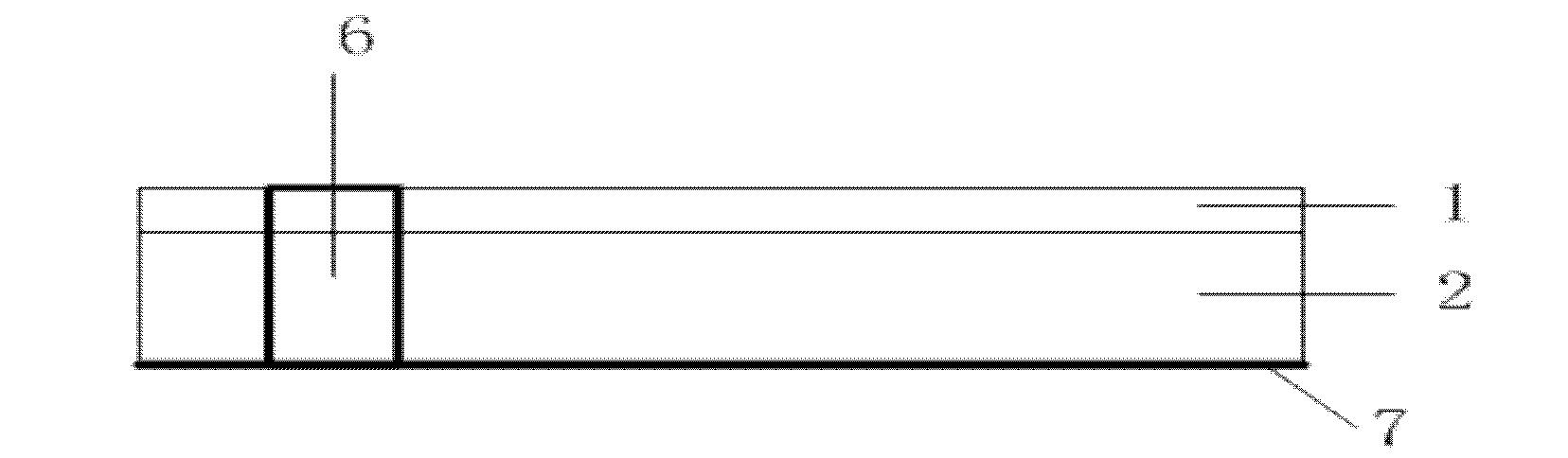
The invention discloses a radio frequency identification tag antenna suitable for a metal surface. The radio frequency identification tag antenna comprises an upper layer dielectric slab and a lower layer dielectric slab which are adhered to each other, a metal layer arranged on an upper surface of the upper layer dielectric slab, a tag chip port formed on a central axis of the upper layer dielectric slab, and a metal earth plate arranged on a lower surface of the lower layer dielectric slab, wherein two sides of the tag chip port are connected with a microstrip feed circuit and are connected with a microstrip radiation unit through the microstrip feed circuit; and two lateral margins of the microstrip radiation unit are connected with the metal earth plate through a short-circuited arm respectively to form a planar inverted-F antenna (PIFE) structure. Under the condition of maintaining a small antenna size, the antenna is in conjugate match with a tag chip at a resonance frequency (915MHz), so that the tag chip obtains the maximum power, and has low return loss in an ultra high frequency (UHF) frequency range, and high impedance bandwidth and radiation characteristics.
Description
RFID Tag Antennas for Metal Surfaces technical field The invention belongs to the technical field of radio frequency identification, in particular to an ultra high frequency (UHF) radio frequency identification (RFID) tag antenna suitable for metal surfaces. Background technique In recent years, RFID technology has been widely used in many fields. It is a non-contact automatic identification technology based on the principle of radio frequency. The working frequency of the RFID system is low frequency 100-500KHz, high frequency 13.56MHz, ultra-high frequency 860-960MHz, and microwave frequency 2.45GHz and 5.8GHz. As the air interface of radio frequency identification, antenna plays a very important role in RFID system. Since the tag is pasted on the object to be identified, the area of the tag is required to be small enough, which requires the tag antenna to have a small size. In passive RFID systems, the antenna is required to be conjugate-matched to the chip to provi...
Claims
Login to View More Application Information
Patent Timeline
 IPC IPC(8): H01Q1/22G06K19/077H01Q1/38
Inventor 唐开元金美佳
Owner 江苏拓元科技发展有限公司